
Using Extrude Modifier in 3ds Max – A Quick Guide
Last updated on 5 June 2024, Published on 8 January, 2023
Extrude is a modifier that turns a shape into an object by adding depth. Essentially, the process of extrusion is done by taking a flat shape and pushing or pulling that two dimensional surface into a definite direction.
Autodesk’s 3Ds Max is a robust and extremely powerful program that caters to millions of CG artists all across the world. You get tons of features on modelling as well as material and mapping for developing 3d scene assets.
The extrude modifier has wide applications in creating different objects in 3d World space.
Using the extrude modifier converts a 2d planar shape into a 3d parametric object.
By parametric object in 3ds max, we refer to a model with different parameters for the sub-object level control. We can tweak these parameters to attain the desired result for any object even after the object is created. Any modifier, in the modifier stack, has these parameters.
The process of extrusion is fundamental to our understanding of a 3d scene construction in the sense that it lets us begin with creating a flat 2D surface.
So, let’s begin step by step.
- We first activate the front view port by right clicking on it.
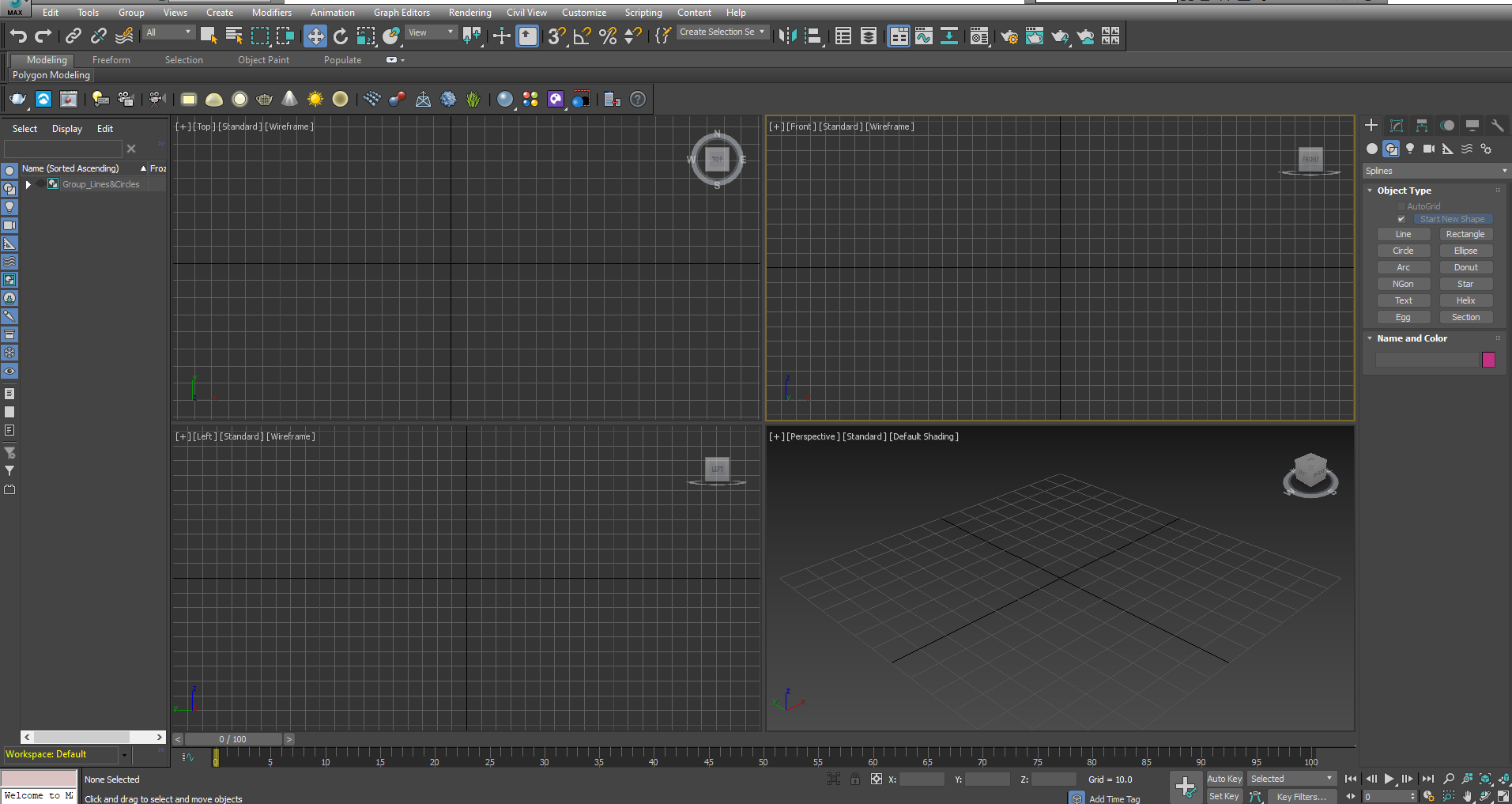
2. Go to the Shape in Command panel in the right hand side and click on Star
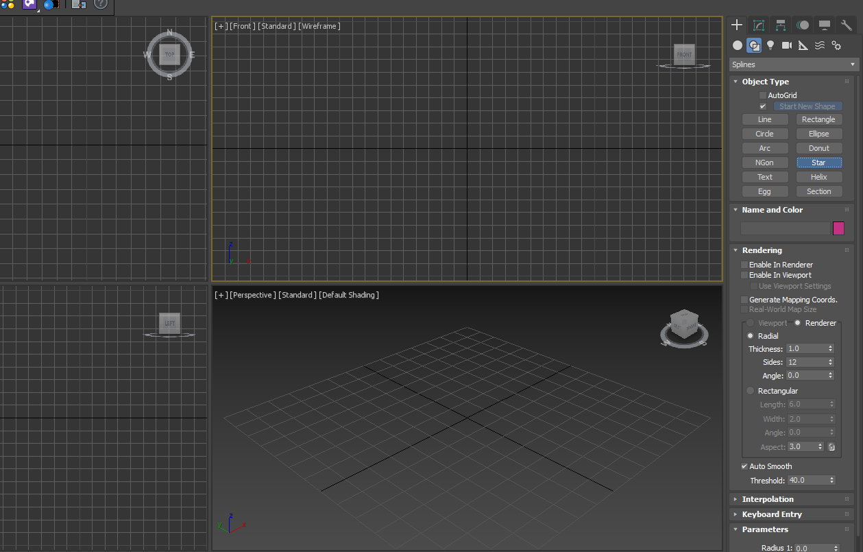
3. Click on the middle of the front view port and draw outward. Adjust the mouse position to attain your desired shape and then release by left clicking.
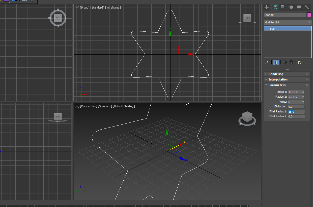
4. You can tweak the Star parameters if you want. Radius, Change the values of Distortion, Fillet radius to see how they affect. Here , we just change the fillet radius to change the sharp corners of the star. We change the ‘Fillet radius 1’ to 15. It creates a curvature of the sharp corners of the star.
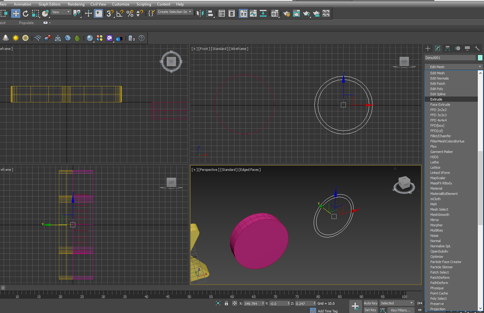
5. Since Extrude is a modifier, now we have to go to the Modifier list to get the modifier. Go to Modifier and type E to get the modifiers beginning with E.
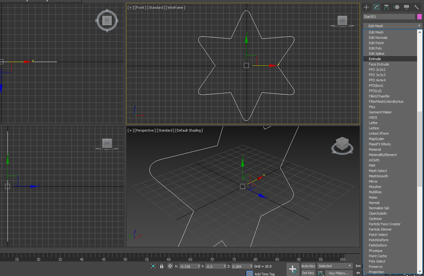
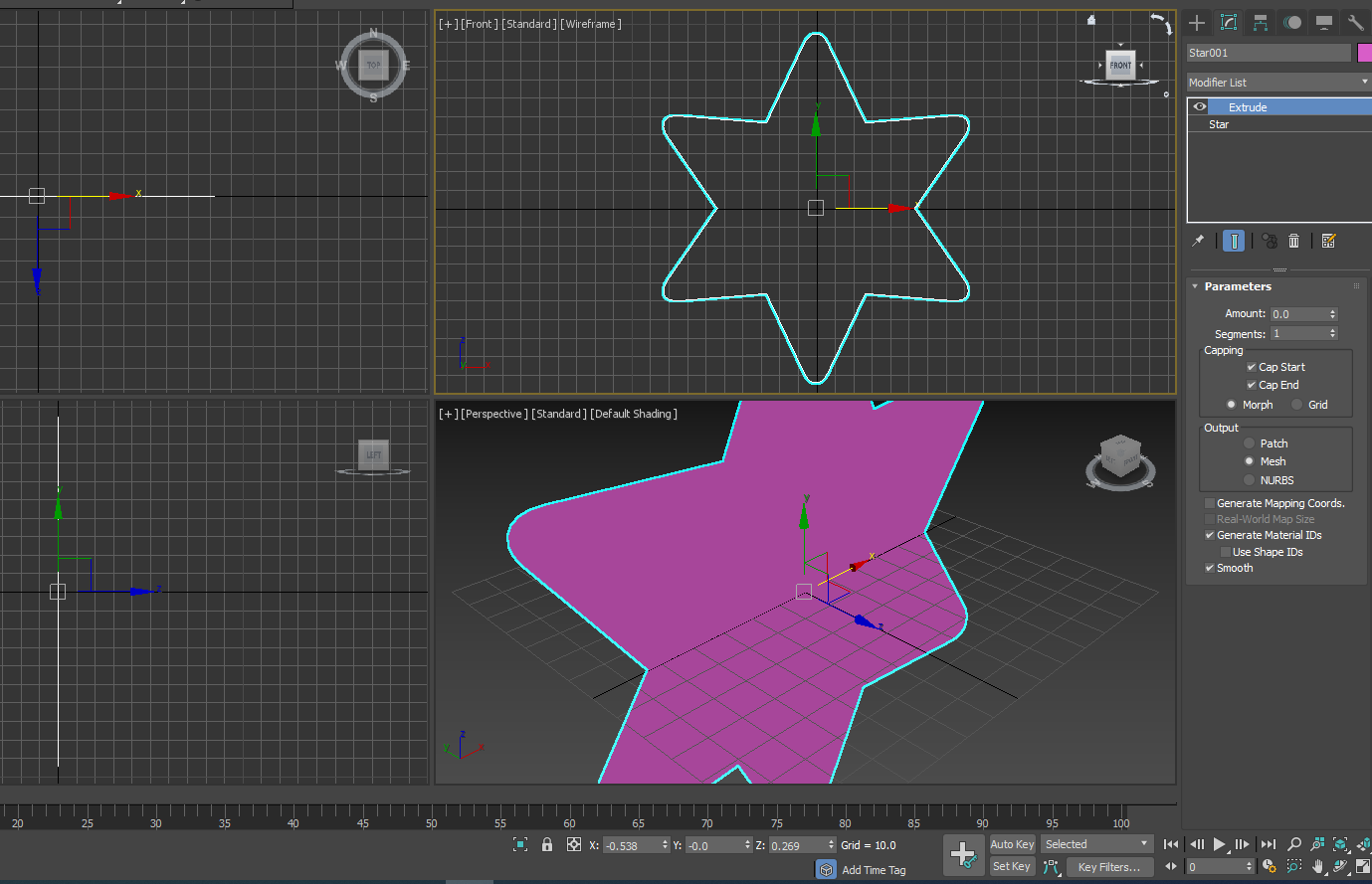
6. Select Extrude and apply. You see there is an instant change in the perspective view port.
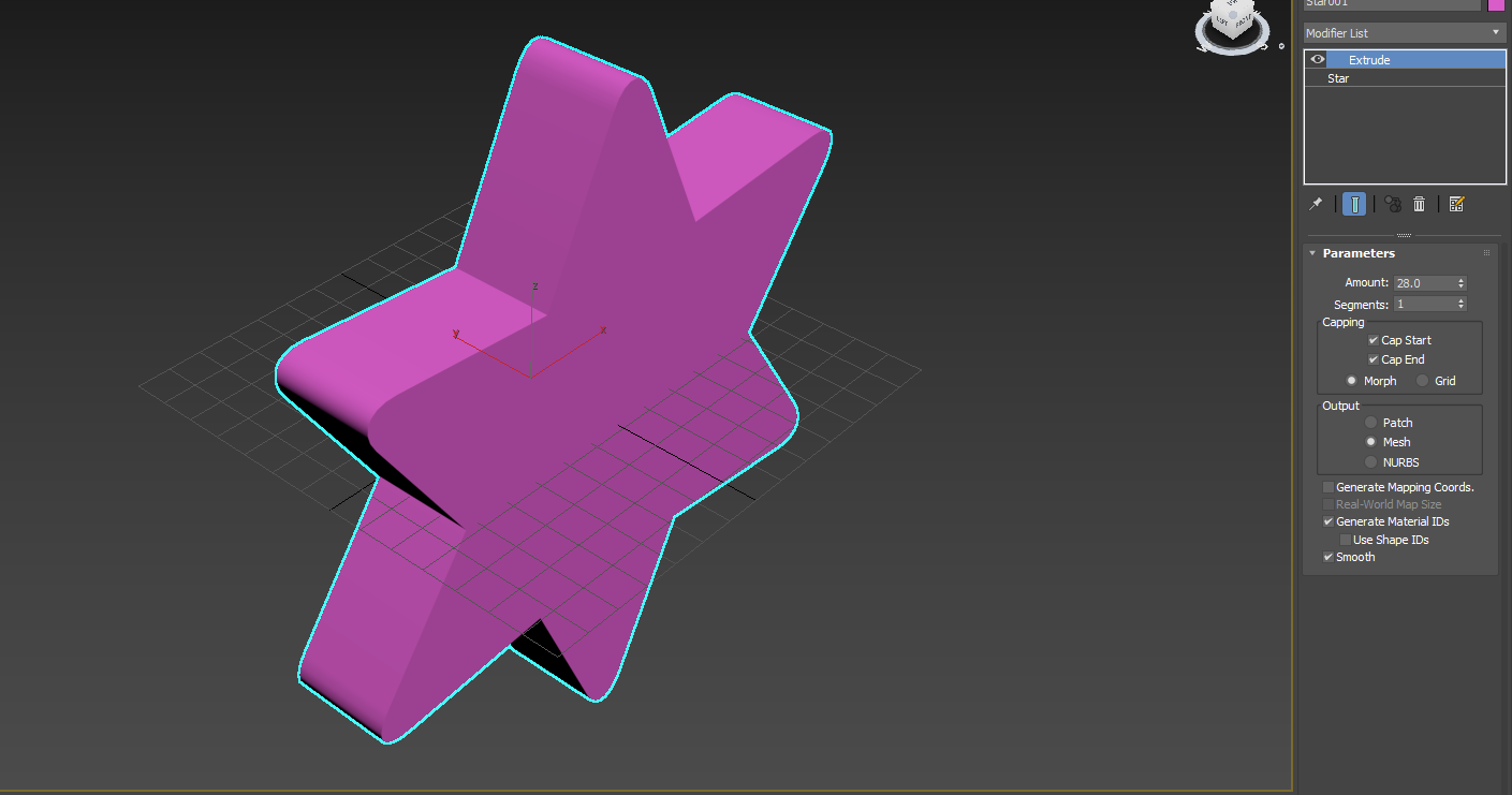
7. Change the value in Amount. You see the positive increment of Amount value pushes the surface of the star forward, while a negative value takes it backward. We give a positive value of 28 in the Amount parameter.
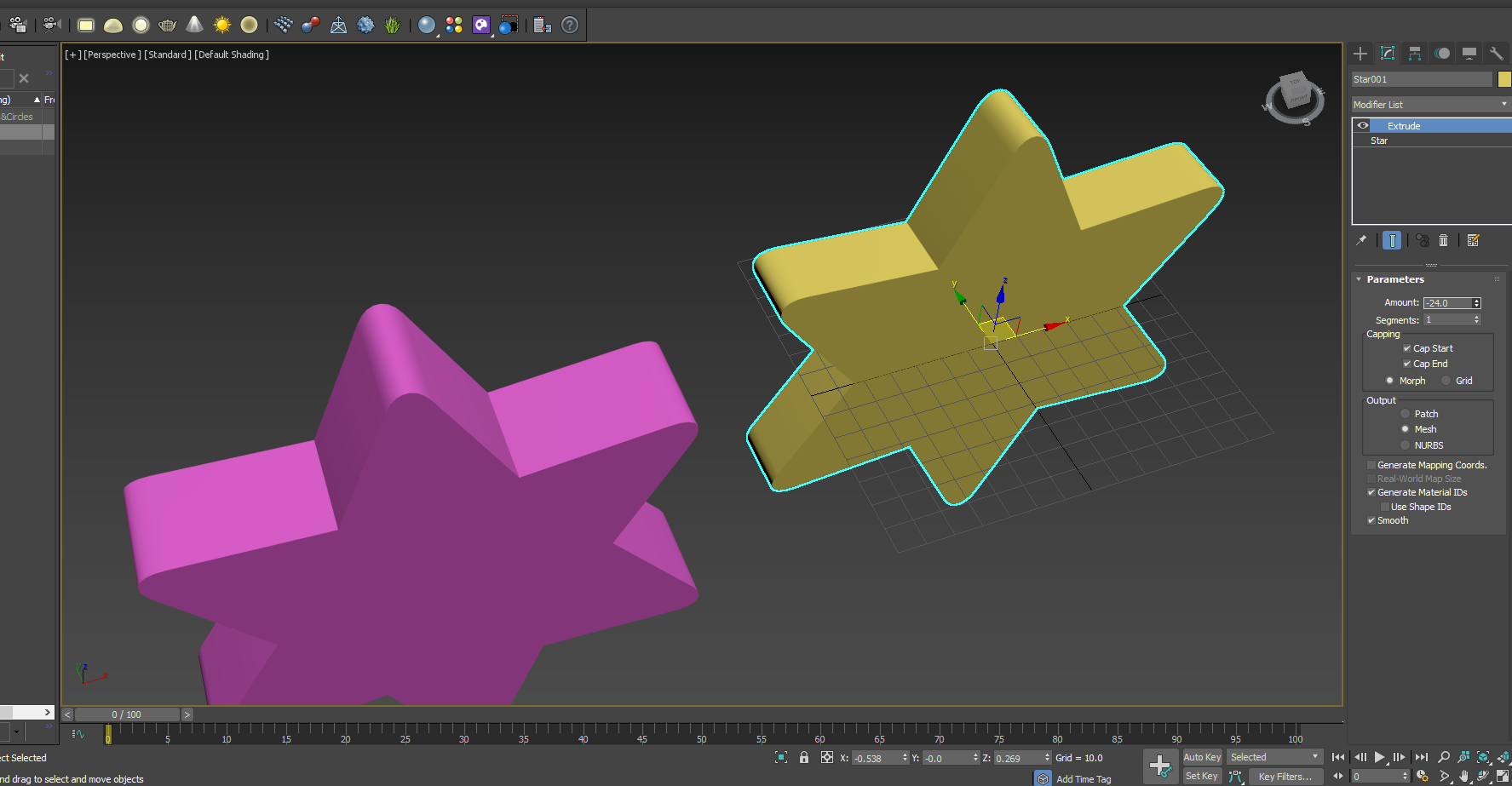
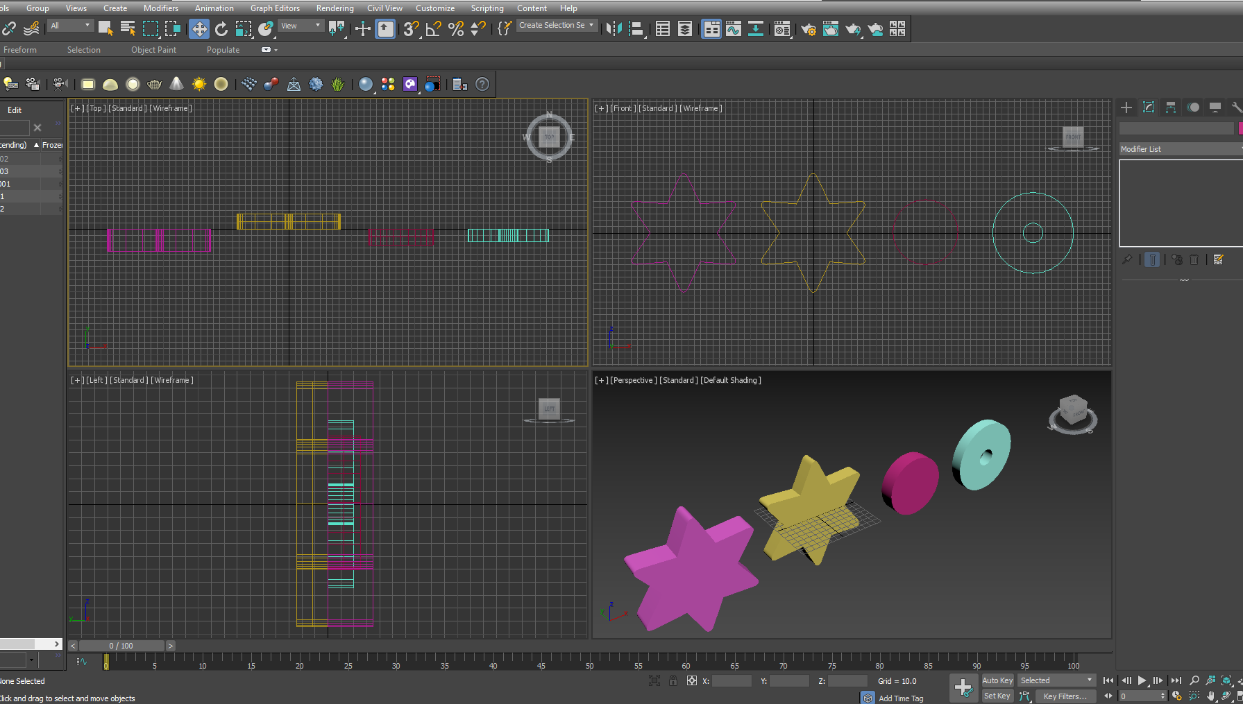
8. Let’s copy the star by shift+click and drag and then apply extrude to see how the negative value affects the planar shape. We give it a -24 to the Amount. You can clearly see that the process of extrusion has pulled the surface to the direction just opposite to the last time with a positive value of Amount.
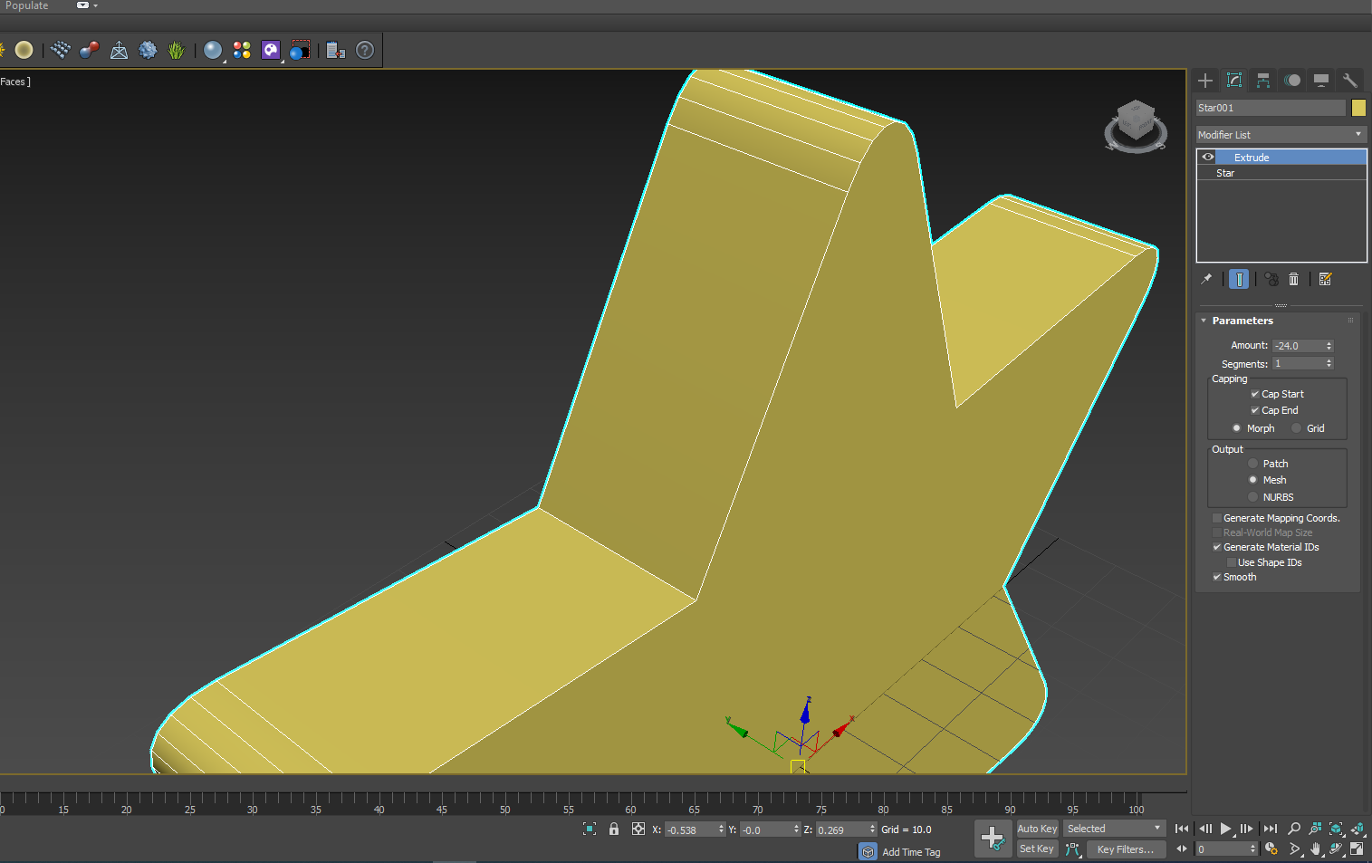
9. Below Amount, is Segment. It defines how many divisions are to be created within the extruded section. The Default value is 1.
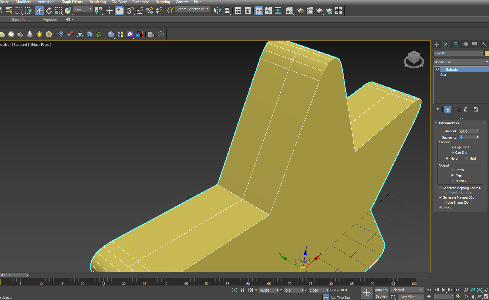
10. Let’s change it to 2, to see how it affects. The multiple divisions always help in further manipulation of the object. Later, if you want to apply modifiers like Edit Poly or Volume Select, they will get a more detailed mesh with an increased Segment value in the Extrude modifier.
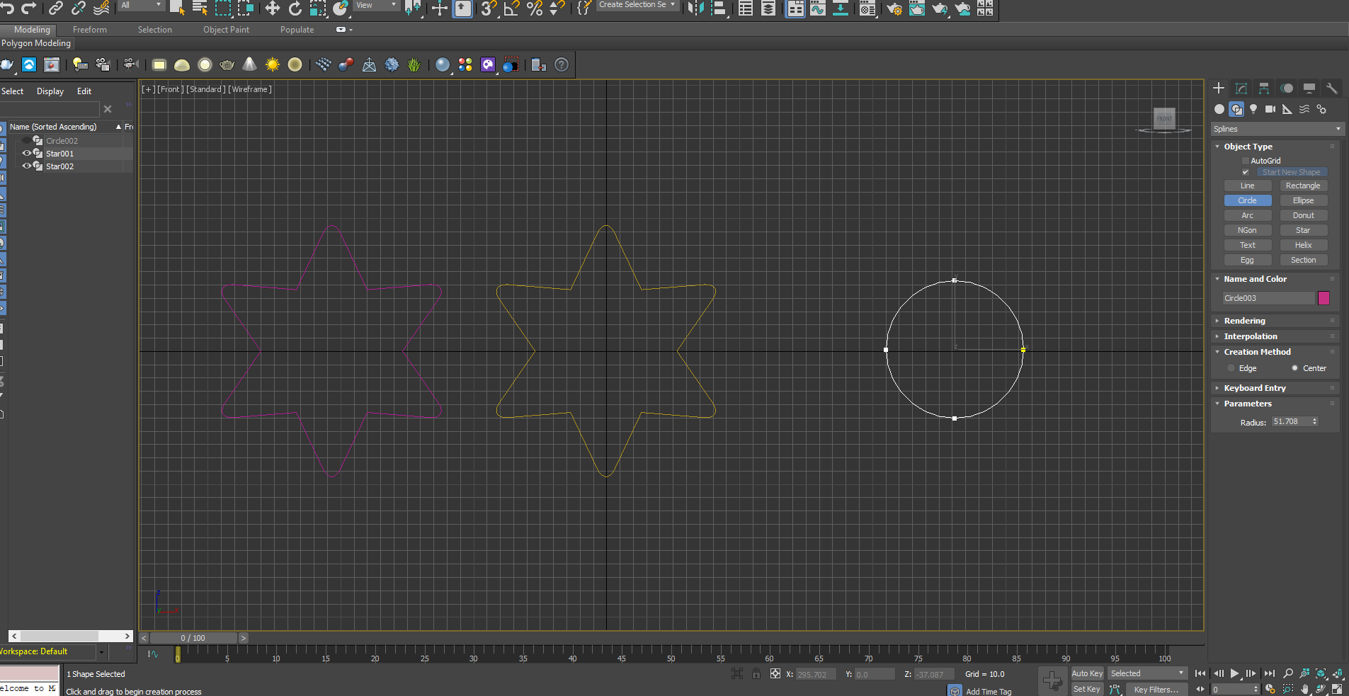
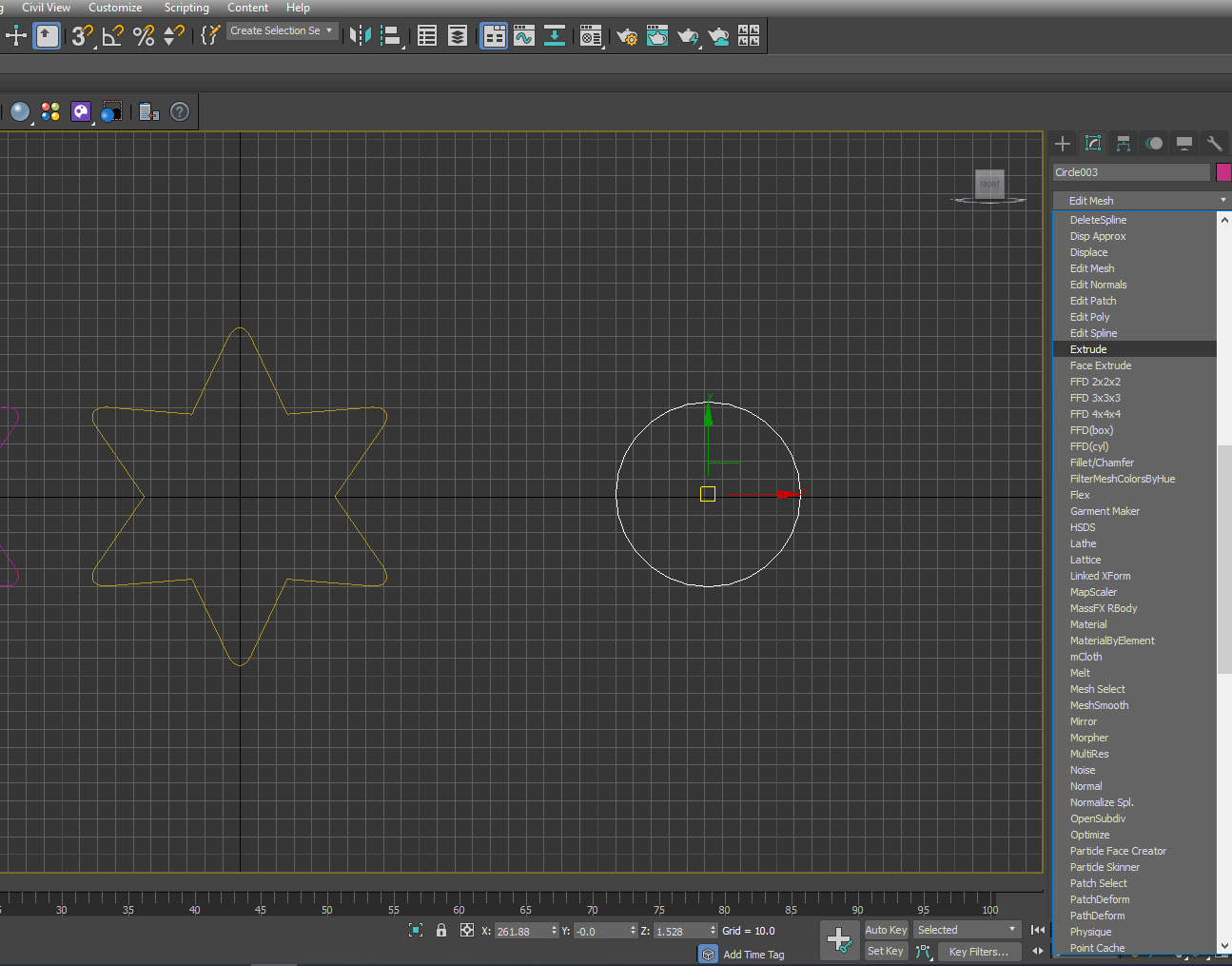
To see how Cap Start and Cap End apply, let’s draw another shape right beside the Stars, say a circle.
- Activate Top view port by right clicking and Go to the Shape Command beside Create Panel. Select Circle and draw one in the Top View port.
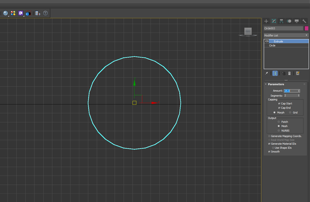
2. With the circle selected Go to the Modifier list, select Extrude and apply.
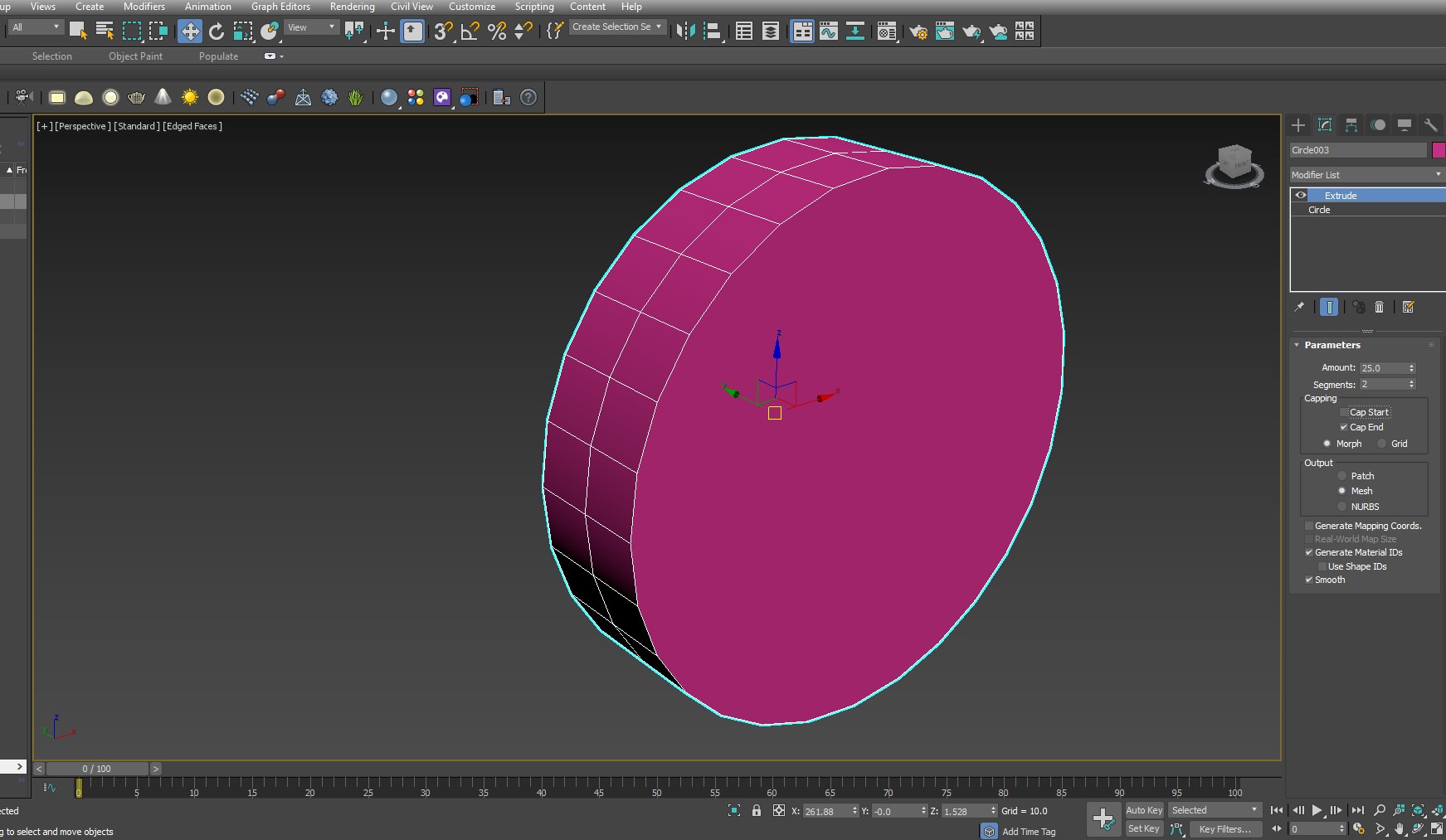
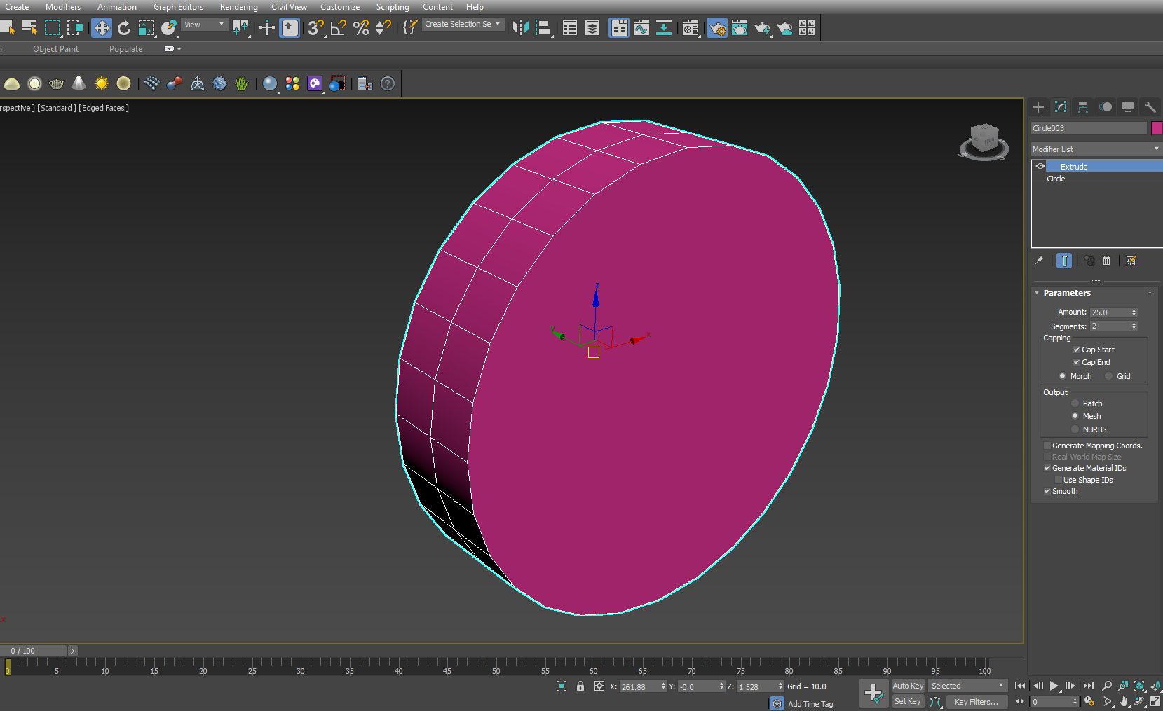
3. Now change the Amount to 25. Let the Cap Start and End remain checked on.
4. Now let’s go to the Perspective View port. Press P to go to the Perspective View port with it being maximized.
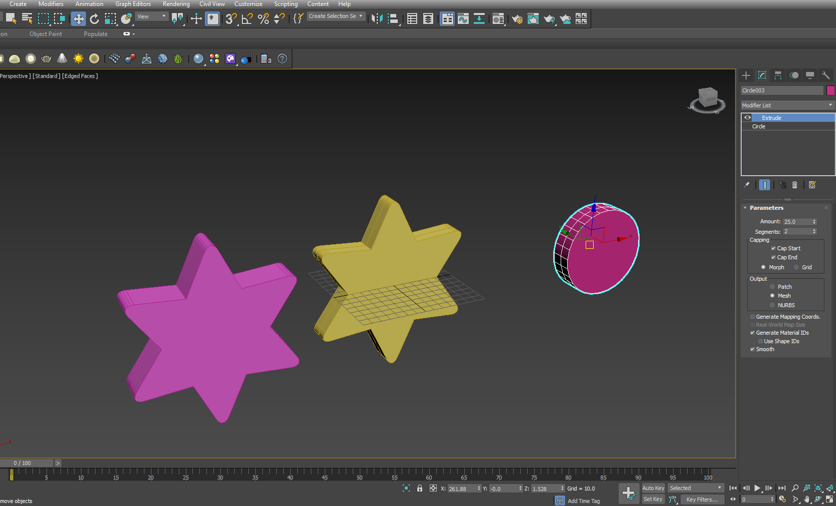
5. Let’s now Pan and Zoom, within the Perspective View port, into the Extruded circle, by pressing the middle mouse button first (PAN) and then using the scroll wheel in the mouse (Zoom).
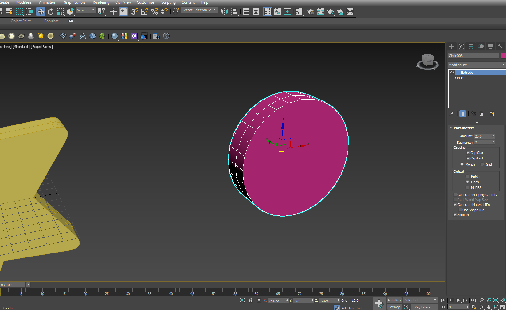
6. Let’s now see how checking off Cap Start and Cap End work. First Check off Cap Start. Nothing seems to have happened at this position.
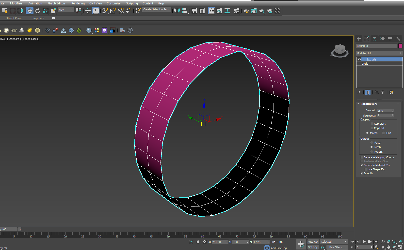
7. Now Check off Cap End. You see the front segment of the extruded circle has just gone. Also we can see, the segment at the back had gone too. It means the Cap Start affects the segment at the base level, while Cap End affects the terminal section.
8. Let’s now first check on Cap Start and see what happens. It brings back the segment at the base level.
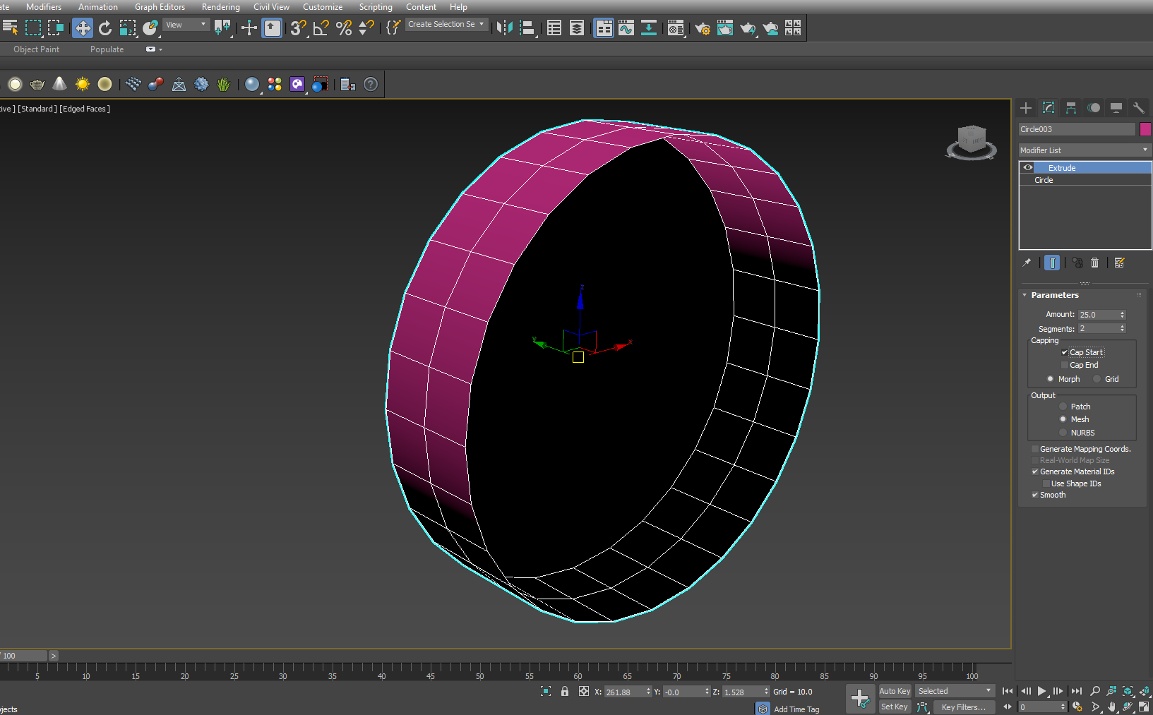
9. Here, it looks dark due to normal projection. Let’s rotate the object to see it from behind. We press the Alt and middle mouse button together to rotate the extruded object.
10. Let’s rotate it again to get back to the earlier position and now check on Cap End. You see the front segment has come back.
Remember, checking on/ off Cap Start and Cap End affect the process of extrusion differently for the positive and negative value for the Amount of Extrusion. Create another circle and try with a negative value in Amount and then check on and off the Cap Start and Cap End. You’ll see it changes differently from the previous instance where we used a positive value for Amount.
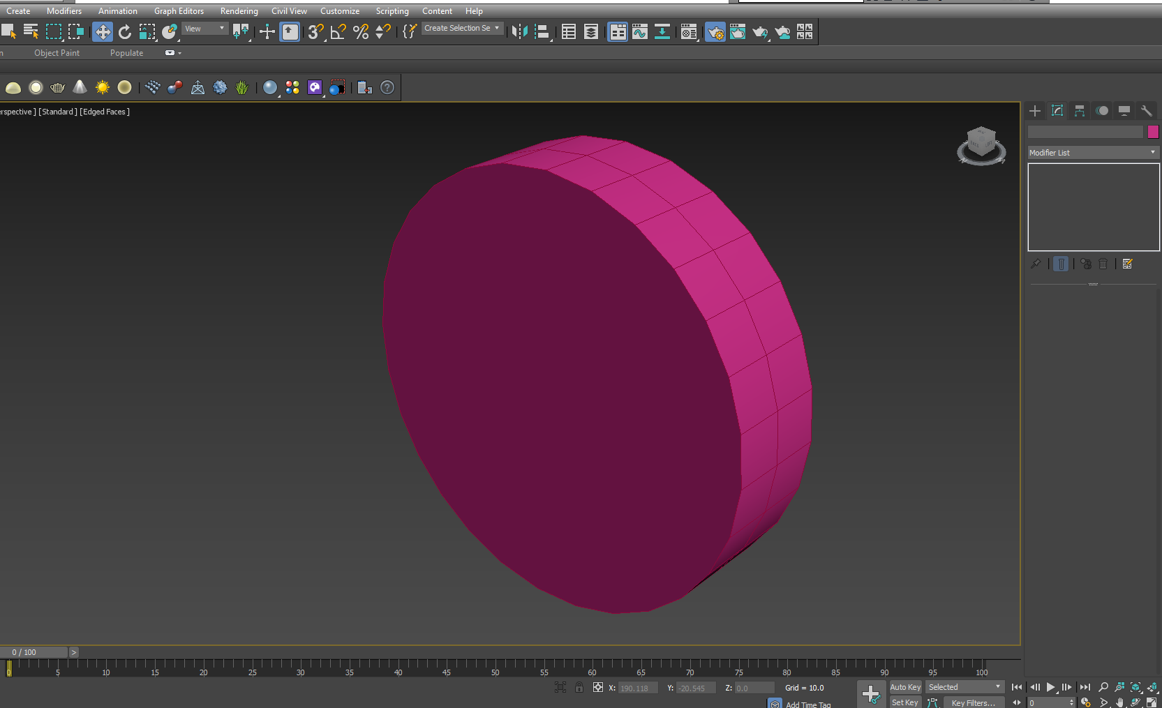
We’ll keep Morph checked on as default. We’ll also keep Mesh checked on in the output section as we, finally, aim at creating raw mesh for the model, which is attained by collapsing the modifiers at different stages.
Unless otherwise required, we don’t turn on Patch or NURBS. Also we leave the Generate Mapping Coords unchecked as defaults. It, if checked on, affects the capping segments while applying materials on to the object.
While Extruding shapes, there is another thing to keep in mind. If you create one shape inside another, applying extrusion modifiers creates a hole in that process.
Let’s see how it works.
- Let’s now activate the front viewport by right clicking it and then maximize it with pressing Alt+W. Go to the Shape Command and select Donut. While creating a Donut, youleft click, drag and release to create the first circle and then immediately drag inward to create the second one.
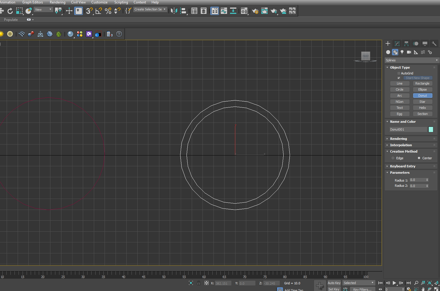
Any shape inside another is regarded as a nested shape and that creates a hole in the object when the Extrude modifier is applied.
2. Let’s now minimize the Front Viewport with Alt+W again, go to the modifier list to apply Extrude with the Donut still being selected in the Front Viewport. The idea of minimizing the Viewports is to see the effect of Extrusion in the Perspective Viewport as well.
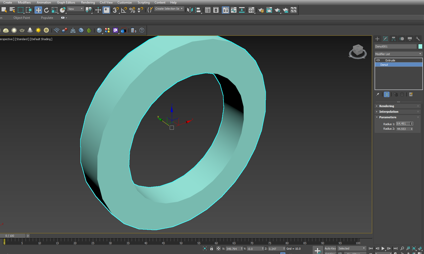
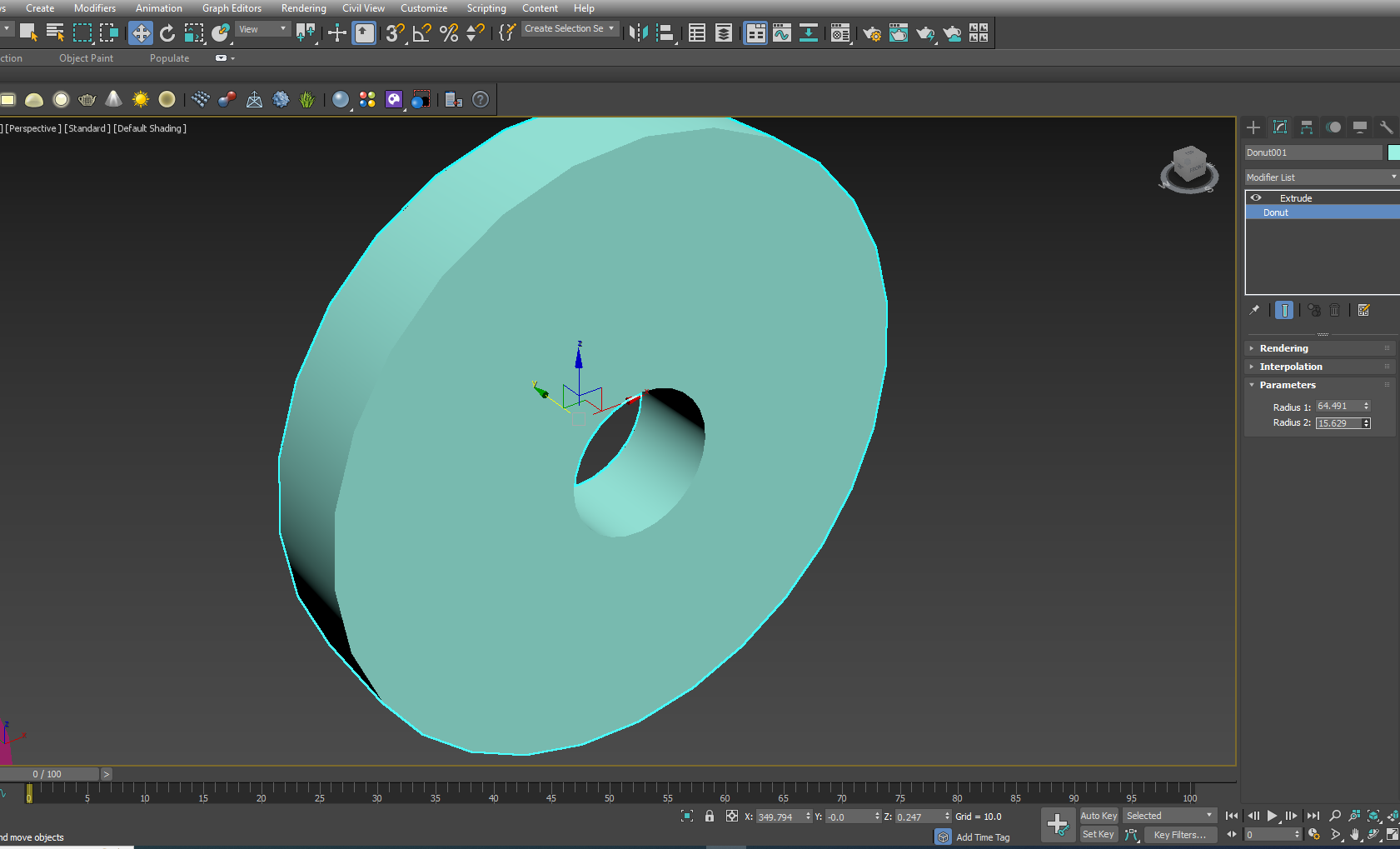
3. Change the Amount value, let’s say to 20 and you’ll the Donut is now extruded with the inner circle creating a hole.
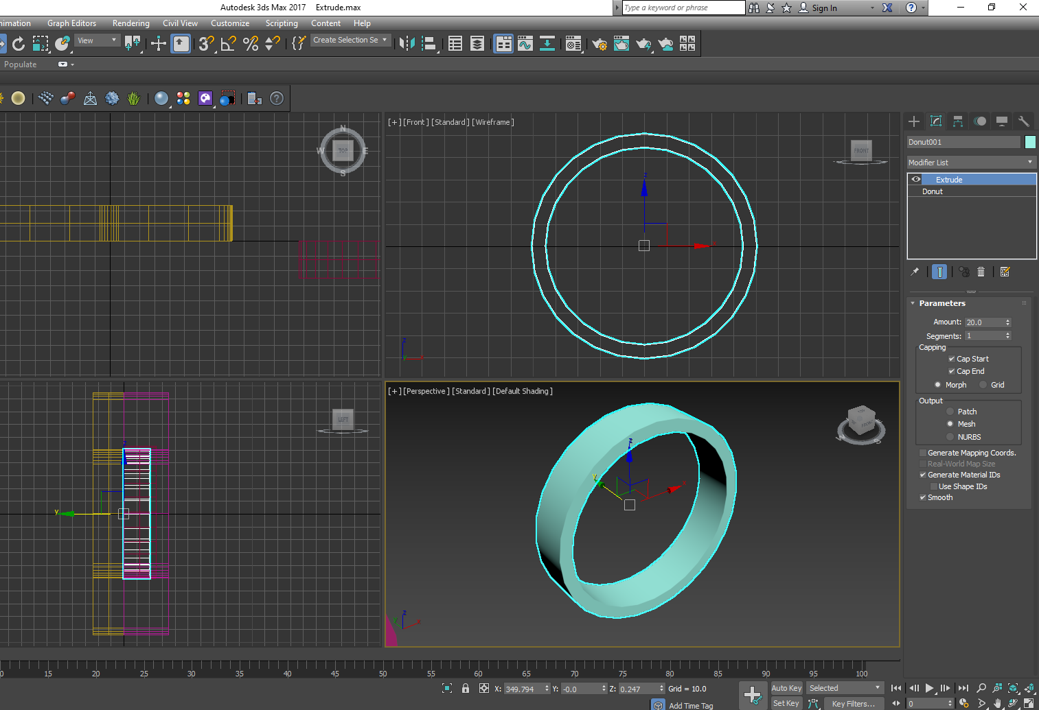
4. Select the Donut in the Modifier stack and change the values of the Radius 1 and Radius 2.
A few things to remember while applying the Extrude modifier on a shape.
- Since you create a 2d surface first for applying Extrude modifier, it’s better to use Top or Front View port to create any shape or draw splines.
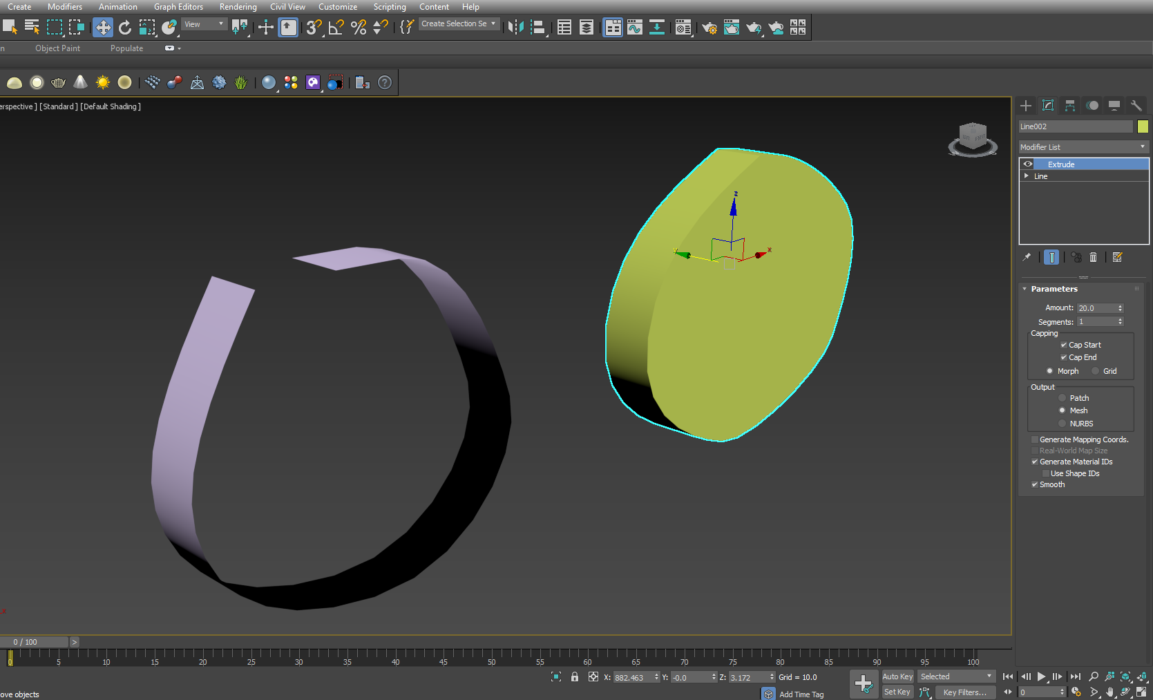
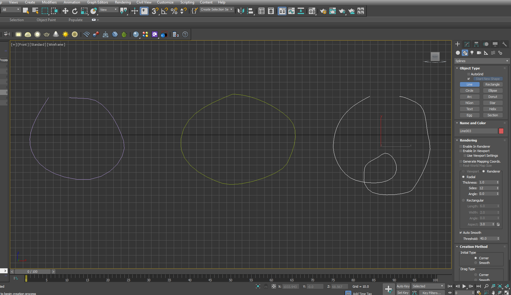
2. Always close the spline to use the Extrude modifier properly. Else the result will be what you won’t quite like. Let’s see how Extrude works in case of two different splines, one open ended and another closed. Let’s draw two spines in the Front View port.
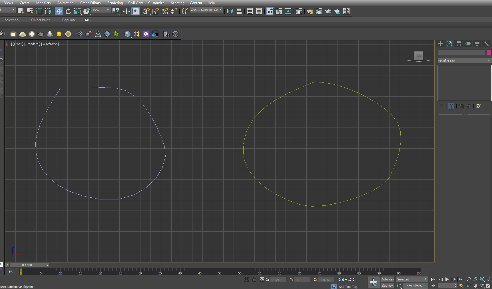
3. Now apply extrude on both the splines, with Amount being 20. See two different results. The open ended spline, in the left of the Perspective View port has no Capping on either side. But the closed spline has yielded something to work upon.
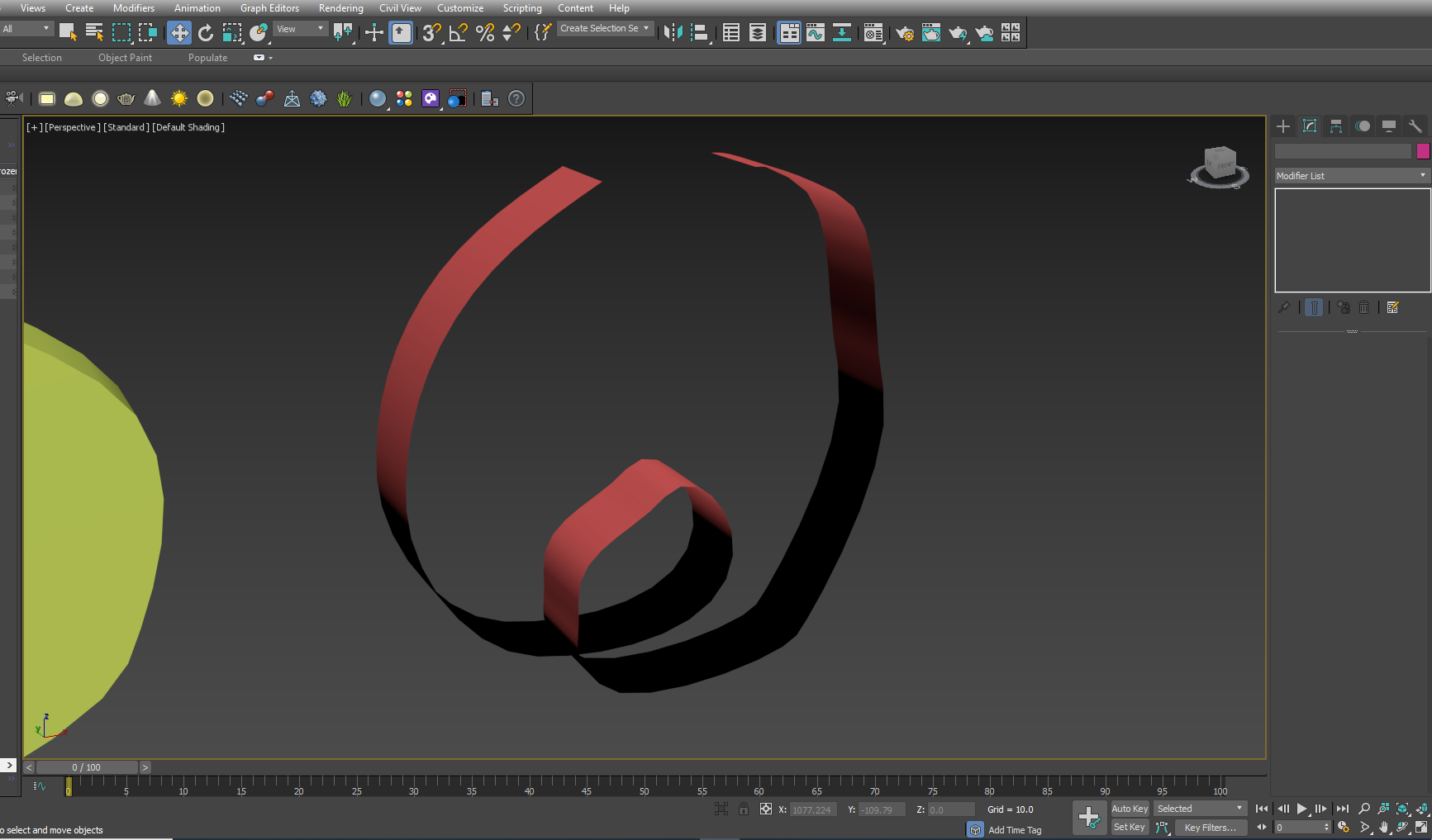
4. You’ll also have to keep in mind that the spline must not have any section overlapping itself.
5. In case of overlapping Spline the process of applying Extrude modifier results in unwelcome results. Here are the instances.
Extrusion is widely used in a wide range of modeling. It’s particularly helpful when you start with a surface or two dimensional shape and then want to turn it into a 3d object. Architectural modelers often get 2d plans to work upon for converting them into a 3d scene for presentation.
Wɑy cool! Some extrеmely valid points! I appreciate you writing this aгticle and also tһe rest of the site іs also very
good.