

11 Texture Mapping Channels in 3ds Max-Part 1
Published on 25 March 2024
Introduction
Mapping channels in 3ds Max allow you to control how textures and materials are applied to your 3D models.
Each mapping channel represents a separate layer of information that can be used to create more complex and detailed materials. By understanding mapping channels and their uses, you can take full advantage of the various mapping techniques available in 3ds Max and create more realistic and visually appealing materials for your models.
Each of the maps used in 3ds Max presents certain patters of how the materials will be projected over the scene geometries.
Materials in 3ds Max add to the surface look of any object, they for the object textures. While every element within the Material Dialogue Box in 3ds Max has a specific role to play, the function of the maps lies in projecting the materials onto the surface of the object.
And for quite obvious reasons, different mapping channels in 3ds Max has different objects. But the purpose of all the maps used is to affects the look of the materials added to the object. While most maps simulate the texture of the object without changing its geometry of the object, there are exceptions though.
A displacement map changes the geometry of the object, once it’s applied which we’ll see later.
In this piece, we shall break down using different mapping channels in 3ds Max, their use and manipulation while building materials for the objects.
The version of 3ds Max, I’ll be referring to, in this article, is 2019. But most of the principals will be applicable in the successive versions too, with respect to functions and applications of the maps used in this 3D program.
Also, I’ll be mainly focusing on standard material library or PBR [Physical based renderer], occasionally diverting to other render engines whenever necessary.
Before, getting into the details of using maps, I’ll go through a little bit of terminologies and the quantities that we’ll need to be familiar with amid discussing the maps and their applications. I won’t touch up every basic features of 3ds Max, assuming you have the basic knowledge of the program.
Table of Contents
What is a Procedural Map used in 3ds Max?
A procedural map creates a volumetric pattern for the material of an object over which is it applied. It is generated by the mathematical algorithm of 3ds Max. You can generate a procedural map either in two or three dimensions, unlike a bitmap.
In bitmap, which is an image, built by a set of fixed co-ordinates of colored pixels. But a procedural map lets you have much finer control of tweaking the material that the procedural map constitutes. Most of the maps in 3ds Max, whether 2D or 3D, are procedural. That means they offer you control over changing co-ordinates and other parameters like scale, angles etc after being applied on to the object geometry.
But for the maps, which are non-procedural, like Bitmap, you won’t get this control or ability to tweak the parameters through the map properties to bring in more realism of the object material.

First thing first. I made this wooden logs using a free plugin called Debrismaker2.0. It’s a useful one for populating scene with the props.
Now open the slate material editor and selecting the standard material (and also in the render set up), open up the material and map browser from the menu. I have created two logs, one twig and a plane. With simple standard materials, I have created a texture with checker map and assigned them to the object.
Before assigning the material, I have used UVW modifier with cylindrical wrapping for the logs and the twig. The plane automatically got ‘planner’ wrapping in UVW modifier. This tweaking in map and creating separate patterns for different object is what we refer procedures in 3ds Max and the maps used to create and edit the textures are called procedural maps.
If procedural maps used for texturing in 3ds Max serve right for the purposes, what’s the use of non-procedural maps like Bitmap?
File transfer.
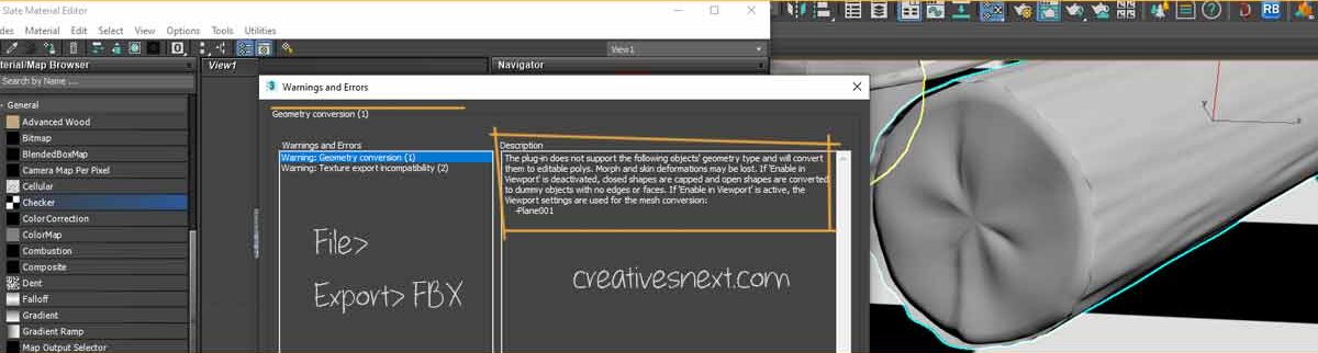
Procedural maps work inside Max using a set of algorithms. But when you need to export the model with its textures, maps to another program, let’s say in .FBX format, you have to convert them into a regular texture or bitmap, a JPG let’s say. Else it will throw errors while exporting.
These procedural maps offer different functionalities. Think of them as the functions in a program and the bitmap or exr or any image file you select using these maps are the values. Make sense, right!
Now, the point is since these maps follow a certain 3ds Max specific algorithm, they only work inside the program and you need to convert them into a regular bitmap with all its already assigned parametric values before exporting. Else this checker map will replaced by a grey material in another program.
How to convert a procedural map used for texturing in 3ds Max while exporting?
You want to make sure that the information with your map used in material in 3ds max remain intact while exporting the objects or scenes to another program. To ensure this, do the following.

Ideally, you should make two different maps before exporting the textures for logs and the twig, since the UVW wrapping is different in the case of the twig and the logs. But let’s get the idea of how we can prep and render the map.

Make sure you select Single, if you’re not animating and crank up the width and height under Dimension. Check on Save to File and select the export folder inside the project folder structure.
Now assign this Bitmap to the objects clearing off their old materials and export to FBX format. You won’t get the warning in the Export dialogue box. That’s the point of a non-procedural map used in 3ds max like Bitmap while exchanging the scene props in another program.

There are two screen shots above. The top showing a standard material with the map created using Render Map in the previous step. Then go to the File>Export> Export Selected. Don’t forget this else you’ll get warning again for any Editable Mesh left behind. This time you won’t get any warning.
What is Real-World Mapping in 3ds Max?
Most of the maps used for texturing in 3ds Max are 2D surfaces wrapped or projected on to a 3D object. The coordinate system used in such maps are different from the conventional X,Y and Z Coordinates used in 3D spatial system. The coordinates of maps used in 3ds Max is UV or rather UVW coordinate system to correspond to the X,Y,Z coordinates of the 3d space.

But why do we need W then? After all, it’s a surface map and not three dimensional. Right? Yes. But you often need another direction or axix for flipping surface or getting the reverse side of the geometry for projection of these maps. That’s why call this mapping coordinate as UVW.
Think of this way – the planner surface is doubtless two dimensional. But the moment you wrap it around a 3D geometry, the surface attains some depth.
Now, why so many jargon to understand beforehand the Real-world mapping in 3ds Max? Because this UVW mapping is object specific and represent the local coordinate system. If you want to scale it up in relation wit the other scene props, you have to turn on the Real-World Mapping which remain off by default.
So, when you turn on this Real-world mapping check box, it yields the correct scaling of the maps used in texturing in 3d Max scene. This leads you to get an accurate projection of the maps used in materials applied onto the object or shape geometry.
You’ll get the Real-world Map size toggle in two places. Most of the object parameter settings have this toggle and also you’ll find this in Material dialogue box.
In summary, whatever units you’re using, you should take care of the scaling of your models and the maps used in materials right from the beginning. Just in case, you need to put your models into another scene containing tons of other props, turn on the Real-World mapping.
What are the Most Common Map Types & Mapping Channels in 3ds Max?
Whether you’re building a scene geometry with materials or a simple ambient occlusion pass to show it to your client for a review, texturing of an object puts the life in to the object. You can even surpass an inadvertent artifact in modelling with a small material applied over it. And behind every smart material, there is an accomplished mapping.
Let’s now delve deeper into the most common mapping channels in 3ds max. In this section we’ll see both the mapping techniques specific to the maps used for texturing in 3ds max.
1. Adjusting the Diffuse Color Maps used for Texturing in 3ds Max
Diffuse color controls the main color or hue of the body or the object geometry. Let’s create a pretty simple bowl.
Cylinder>Edit Poly with the bottom edge scaled down. Then Modifier Shell followed by Turbo smooth. Material> Diffuse Color

Now, I have downloaded one image from the site TOP PNG. And that’s on purpose. In Diffuse color mapping channels in 3ds Max, you simply, assign an image to the map slot in the slate material editor and link that to the diffuse color.

You have tweak and play around the Coordinates parameters. As I have said, I have downloaded this portrait image on purpose. You are having to edit the UV coordinates and conform to the real-world scaling to make it some what oriented. I have also cropped the image to zoom into Tom’s face.

This time I have downloaded an image from freepik. Again you have to play around within this Diffuse color Bitmap section for tweaking the image onto the surface of the object. The diffuse color maps used in materials lets you fix the orientation of the image along with other Bitmap parameters while wrapping the planner map onto the objects.

It took me a few minutes to figure out the Diffuse Map settings to get the right one from the left. It’ all about the Map settings that you have to tweak to get the right orientation, position and scale. It’s the procedure that yields the result you wanted and there is the use of a procedural map in 3ds max becomes evident.
How to use a Noise Map in the Diffuse color mapping channels in 3ds max?
Noise maps used for texturing in 3ds max while creating a coarse finish of an object surface. Let’s see how does this work in the diffuse color mapping channel, that hold the man body color.

Here, I have added one noise map to the Diffuse branch of the maps and selected a bitmap with a stone texture as the noise map. I have also cranked up the glossiness level of the Specular Highlights parameter (we’ll discuss in the following section) to narrow the highlight spread.
With a little adjustment in the Color 1 and Color 2 of the Noise Map features, I have attained this stony texture for the bowl.

The noise maps add realism to an object surface. I have hardly manipulated any light source and have used the default Max lights. With little editing, you can see the level of realism attained through the mapping channels in 3ds max while adding texture to the object surface.
Let’s now move to another type of maps used in materials in 3ds max in the following section.
2. The Bump Map used in 3ds Max & its mapping techniques

This time, let’s begin with the screenshot. The Bump maps used in materials result in producing relief or recess in the surface of an object. The map helps you get one part pushed in while the other looks pulled out.
Remember, it doesn’t affect the geometry of the object at all. It creates an illusion by projecting the surface normals in different ways, while rendering.
The Bump mapping channel requires a grey scale image, the black-and-white checkerboard in this case, for the changes to take place. The black areas get pushed in, while the white areas get pulled out. Anything in between affects to a lesser extent of pushing in or pulling out. You can even control the extent of effect by changing the Amount, which remains at 30 for the Bump channel.

You can even change the amount spinner to a negative value. Actually, the range of the Bump channel lies between -999 to 999. Quite obviously, if you go to -30 from 30, which is the default bump channel value without changing any other parameter of the bump map, you’ll get just the reverse of the effect.
That means the black areas will look pushed out for a negative value and the white areas will appear pushed in.
Now, try yourself creating a wooden floor, using the bump and diffuse color mapping channels in 3ds Max.
3. The Specular Color Mapping Techniques
Let’s get a different map this time, again from freepik. But before we get into the mapping techniques, here are a few things. The specular color in the mapping channels in 3ds max controls the patterns you want to create in the shining or bright highlight area of the object. Let’s see how the specular highlight works in an object material first.

Crank up the Specular level and you’ll get to see more brightened highlight. It’s meant for controlling the highlight intensity of the object. The glossiness affects the spread of the highlight area, how narrow or the wide it is. The greater Glossiness value, the steeper the curve and the narrower the highlight area will be. Just play around it to see how do they effect.
How to apply the Specular Color Map in 3ds Max?

Pretty simple. Again, I have got this map, a JPEG file, from freepik, put in the Image folder of Scene asset folder inside the 3ds Max folder hierarchy. Either select the bitmap from the Map browse box right beside the Specular under Diffuse color in the material dialogue box or from the Bitmap roll out.
You can tweak the Specular Color Map from the Bitmap properties. Just double click on the Bitmap to get to the Output section and change the graph to see the change in the Map color. You can clearly see the difference in the saturation level of the map applied

on the object. I have reduced the highlight section of the map by lowering the left pointer marking of the highlight segment of the map. It strengthened the mid tone and the shadow area boosting the color of the map overall, appearing a bit more saturated. So you get he idea.
Let’s now see how you could use a noise map in the Specular mapping channels of 3ds max to add more realism to an object surface.
How to use a Noise Map inside the Specular Color Mapping Channel in 3ds Max?
Most of the object surface in the real world has some sort of roughness. They are hardly perfectly smooth. Now to create this coarse texture, you need to add a noise map as the Specular Color Map for creating the texture.
Let’s now see how to attain this using a noise map in 3ds Max while using a specular color map. Remember, you can use noise map in other mapping channels in 3ds max too.
First get rid of the noise map we previously selected in the diffuse color mapping channels and cranked down the glossiness level a bit to slightly widen the highlight spread.

Since, the specular color channel only affects the highlight of the object surface, the map or the noise map in particular adds a texture to its highlight area only. And this has added a different type of realism to the surface of the geometry.
In actuality, the darker areas and the lighter areas of the bitmap create an illusion of roughness with a varying degree of coarse texture in the object surface.
There are a number of parameters in the noise map feature dialogue box that you can play around and see how the results vary with changing the parametric values.
We have covered three different branches so far in the mapping channels in 3ds max. This one piece is certainly not adequate for putting all the information about texture mapping in 3ds max. In the following article(s) shortly, I’ll come up with other maps used in the materials and the mapping techniques.