

Medical Illustrations with 3ds Max [Case Studies]
Published on 11 April 2024
Introduction
Although it’s not the holy grail any more, but medical illustrations using 3ds Max is certainly one of the most coveted bastions for its users and CG artists.
In this piece, I’ll discuss a few techniques, in keeping with the reference images, for building some models and their surface textures. I’ll also take you to After Effects while dealing with some compositing tricks that make the illustrations what they finally look like.
Since I’ll primarily focus on the inherent resources of 3ds Max, there could be some differences in the final render of illustrations. The idea here is to demystify the sequence of works that takes place and help you with the patterns essential for creating such organic things.
I shall use Max’s standard (scanline) and PBR material and engage mostly with the scanline renderer. Although, I am pretty sure that, with the kind of finish that we see in the collage of the header image (collected from freepik for reference), Vray or Corona as the material or renderer will be the most preferred choice.
The compositing techniques I’ll be dealing here will call for some operations in After Effects. Also, I am assuming that you have a good operating knowledge of a 3D program (preferably Max) while following along with this article on the Medical Illustrations and compositing using 3ds Max and After Effects.
Without any further ado, let’s dive in.
You can use 3ds Max 2019 and After Effects 2022 to follow along. The older versions may also do, as I am using standard material with the Scanline renderer and will explain the procedures that you can create the files with. Another thing, I want to point out is I’ll rather focus on the material, texturing and shaders and not on the modelling itself.
Table of Contents
1. Create Micro-organisms with 3ds Max
Let’s start with a pretty simple and basic thing. The microbes and bacteria are widely common representation in medical animation and its visualization. Let’s first see the reference image and analyze.

Features
- A collection of similar microbes – Both models and Materials/ Textures.
- A background – either to add as an environment map in the Render Set up of 3ds Max or inside After Effects.
- There is a typical light shader, directional. We’ll have to create this using the Fall off Map which we’ll see shortly.
- Some of the microbes are in focus and some are not. This is pretty simple with a camera blur, either in Max or in After Effects.
Broadly, these are the things that see in this reference image in relation to our work. And the need this analysis holds for any such illustration, for that matter. This helps you go step-by-step without scrambling and eventually messing things up.
Create a Model for the Micro-organisms
Since you have a really good operating knowledge of 3ds Max, we’ll kind of do a rapid without missing the technical nitty gritty.

First, let’s use Extended Primitives > Capsules. Create one with your preferred settings.
I have added, apart form the Diffuse color and a moderate Specular Level, a noise map to the Bump channel, with 50 as the amount. This helps us get this curvy texture on the exterior surface of the microbe.
In the Noise Map roll outs, I have assigned Tiling for all X,Y and Z as 85 and Noise amount as 50. Also, I put 2 for the Levels. Now compare with the reference image of the microbes we’re using for this medical illustrations.
See the model and textures already looks somewhat close to the ones in the reference image. And now we’ll focus into the light shaders that’s a distinguishing feature for most of the medical illustrations.
But before that , we have to get rid of any Specular Highlight. I added a little for the purpose of preview only. Let’s crank it down to zero.
Create a light shader for the Model – Add self-illumination and Falloff Maps

Keep the Noise map in the Bump channel intact. We have already reduced the Specular Highlights to zero. Now, turn on the Color inside Self Illumination and add one Falloff map in the empty space of the Slate Material Editor.
We have to use this Falloff map in the Map browser of the Color in the Self-illumination tab, we just turned on. Now add this to the Self-illumination branch of the Mapping channel dialogue.

Here is the idea behind using a Falloff map in the self illumination channel. The surface that faces the assigned direction (the Falloff Direction) accepts black or the base color of the model i.e the Diffuse color. And the surface that is away from the Falloff Direction shows white.
In this, the Mix Curve has a role to play in minimizing the white shade of the microbe surface that’s created by Falloff color (white).
Adjust the Falloff Map parameters & tweak the Mix Curve Nodes

Change the Falloff type to Frensel and adjust the Mix curve by adding a few nodes to reduce the area of white shade across the microbe’s exterior surface. See, already you’re closing in the making of micro-organisms with 3ds Max.
Note that, while doing the medical illustrations, you may need to spend some hours tweaking these different values, cranking up and down.
Now keeping with our reference image, the point here is to consider how to make a collection of such microbes with such rim lights coming from a certain direction. For that we have apply another trick.
Add another Falloff Map to the White Color Map of the Falloff – Adjust the Mix curve

Let’s see what actually took place. This rim light is very common in the medical illustrations to make the subject matter stands out.
I have added another Falloff map to the white color which is other than the front side viz. black. This has refined the spread of the rim light along the edges of the object. Also, I have tweaked a the Mix Curve with a few nodes to controls the intensity of the shaders.
How to change the color of the Rim light around the edges of the micro-organisms while creating medical illustrations using 3ds Max?
You may need to alter the hue of the rim light to conform to the background or environment. 3ds Max, as usual, provides with plenty of tools for your convenience and it’s pretty simple.

Within the Output roll out, check on the Enable Color Map, and select the RGB (not the Mono this time). Add a few nodes to the color curve and tweak. I have just about added a shade of hue. You may need to increase hue according to your need to conform to the environment.
The rim light we have created has a kind of omni-directional spread around the micro-organisms. And this may not look very realistic, if we consider that the source of light is at a particular side of the objects. So, you may need, at times, uni-directional rim light along the contours and edges of the objects while doing the medical illustrations. Let’s now see how to do that.
Create uni-directional Rim light around micro-organisms with the Point helpers

Now, quite a few things I have done here to create that uni-directional rim light. Let me point them out step-by-step.
- Select the first falloff map added to the self-illumination branch.
- Select the Falloff Type : Towards/ away
- Falloff Direction: Object
- Tweak the Mix Curve in such a way that the Rim light gets created in one side with a sleek and narrow white spread. See the image. Play around with the Mix curve nodes to get to such Rim light spread.
- From the Command Palette, get to the Helpers and select point.
- Create a point helper somewhere in the view port. Place it in such a way that it remains in a direction and away from the collection of the objects.
- Finally, from the Mode Specific parameter in the right of the Slate Material Editor, click on None and pick the Point helper in the view port. You’ll see the Object shows the Helper name (point001 in this case).
Let’s now see how it has come out.

Create an Environment Map as the Background for rendering the micro-organisms with 3ds Max

Here are the steps.
- Right click on the empty space of the Slate Material Editor and create a Map node with a bitmap.
- Open up the Environment dialogue box by pressing ‘8’ or through the Rendering menu.
- Assign the Bitmap node to the Environment Map under Background.
- Tweak the Offset, Tiling and other features of the Bitmap (double clicking it) to adjust the background according to your need.
This environment is not a realistic one and I have used it just to show that the rim light, though not perfect, kind of blends with a background image.

Finally, I have tweaked changed the Noise type to Turbulence, cranked up the Size to 80 and tiling to 90 to impart a more curvy texture of the microbes’ surface. Also, reduced the strength of the falloff distribution.
You may or may not play around depending on your need.
2. Build Double Helix Strands of DNA with 3ds Max

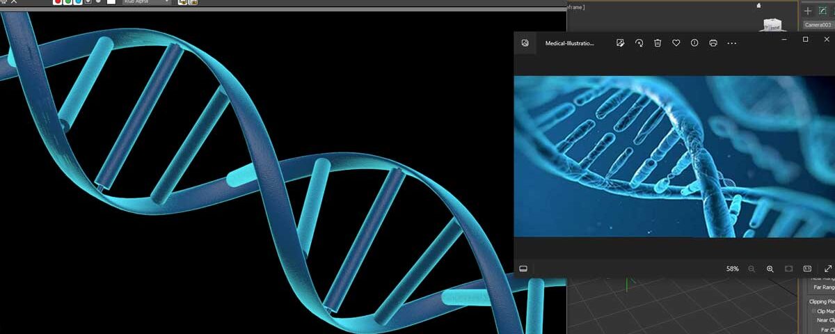
Let’s first see this pair of reference images and analyze. I have got the thumbnail in a Nat Geo video recently (the image on the right). If interested, you can watch it out here.
Features
- The image on the left – One pair of helical strands in the middle and are sharply in focus. The other ones are blurred and in the background. The background is certainly composited either in After Effects or in a similar program. Some light leaks were added with the darker particles floating around. We can use the effects or plugins for particle generator to bring such fluid sim impression.
- The image of the right – It offers much more clarity with an extreme close-up. An interesting case for material and light shaders. Like the other one, one is in the foreground and other ones, scaled down and off-focus in the background.
I like to focus on the Nat Geo image first. Note that, I won’t get into modelling of this DNA, as I already said, I’ll rather look into the material and texturing of the objects, emphasizing on its different shaders while talking about the medical illustrations using 3ds Max.
Let’s bring a model of the double helix strands of DNA
I have downloaded one DNA model from a turbosquid page, just to minimize the time for modelling. But before working on that model, I would like to highlight a few things regarding this Nat GEO thumbnail image I have brought in as reference.
See in the case of medical animation, this rim lighting around different objects is very common. It highlights the model of the organ and puts it in the foreground. Now how do you achieve this?

We have already discussed. You have to add a falloff map to the self-illumination channel and then adjust the settings of the Falloff map. If one falloff map is not adequate, then you may have to add another falloff map to the White map of the first falloff map.
This helps refine the White spread of the 2nd falloff map that results in such shaders. You can attain this marine blue shader by enabling the Color map and adjusting the RGB graphs. Before arriving at the scene with our turbosquid model, let’s carry on a test upon a cylinder.

Let’s see what I have done o this cylinder. After having set the Diffuse color, first I have added a noise map to its bump channel. Look at the DNA image, there are many scratch over the surface. Not sure, if that happens in actuality, but let’s follow what are there.
You can create the illusion of relief and recess using noise map in the bump channel. I have added a grunge bitmap downloaded from a freepik page to the images folder within the sceneasetts folder to add this as a noise map.
Then I have added a falloff map in the Self-illumination branch. See I have obtained rim light shade around edge of the cylinder. To tweak the color of the shader I have enabled the color map and then adjusted the RGB.
It’s not perfect, but our idea is to figure out the pattern and get as much closer as possible. And now we’ll proceed to the double helix strands of DNA for our purpose of medical illustrations.
I have applied the material used on the Cylinder over the DNA model with little more adjustments with regard to the falloff distribution. It’s still not that close, but we’re on the right track. Let’s see what the falloff distribution looks like.

I have used standard material with scanline renderer. I am pretty sure, with Vray, Corona or even with Arnold renderer and the PBR material it would already have been one of the presentable instances of the medical illustrations using 3ds max.
I won’t spend longer to make it perfect at this point. May be I’ll come back later and work on it again. But you get the idea of tweaking the falloff distribution to get the shader that we saw in the Nat Geo reference image.
Add another falloff Map to the First one to refine the shading spread
You can use a point helper to control the shading assigning a direction.

Here, I have added another falloff map to the white color of the first Falloff map parameters. I tried to induce an omnidirectional shading like the Nat Geo reference image.
Conclusion
This blog is no way over and I’ll continue publishing more articles following what we have covered here, mainly the application of the falloff map to create shading around the object commonly seen in medical illustrations using 3ds Max.
There is a hell lot of compositing to come shortly where we’ll play around the models in obj or fbx format inside After Effects. The idea is to figure out different tricks and techniques medical animation with 3ds Max and After Effects. As I mentioned, I won’t focus on the modelling primarily at this point of time, but rather on the material, texture mapping and shaders.
Please let me know your take on this piece if you want anything particular. Hope you liked it and please do not forget to share.