
How to Create and Animate 3D Chemical Structures using Online Databases – Part 2
Last update on 5 June 2024, Published on 20 February 2023
The second and concluding part of this series offers more options to the content creators for making 3D chemical structures. Here, we’re using Jmol (with step-by-step guidelines) and other programs to show how you can create chemical structures and then use them in programs like After Effects and 3ds Max for animations. Also, we’re diving deeper into online chemical databases showing how you can obtain molecules, data, and structures.
Introduction
3D chemical structures always add a dimension to any science video or animation, in terms of the authenticity of the subject and visual appeal as well.
As we are continuing Part 2 of this series on How to create and animate chemical structures in 3D using online databases, here we’ll dive deeper into animation and compositing with the three-dimensional molecular structures that we obtained from different sources.
We can use these small pieces of animated videos with 3D chemical structures in different explainer videos across the board. Be it for producing e-learning material on chemistry lessons for schoolgoers or an animated presentation for a drug manufacturing company, a structural presentation of molecules in 3D is something that we often require.
In Part 1, I have discussed how to use Jmol to create 3D chemical structures and online databases like PDB or PubChem to obtain different molecular structures in a format acceptable to Jmol.
Using these databases is an essential thing that content creators must have a hold on to. Your client may come up with a 250-character IUPAC entry and if that suddenly lands you nowhere, then you’re gone. So all you have to do is you have to know how to use these databases to obtain any molecule and then you may access some programs to either create an image file in PNG or JPG or generate the files in 3D format.
And that’s exactly what I discussed in great detail in Part 1. Also, as we saw (in Part 1), we can’t get the 3D rotation with exported PNG or JPG images in After Effects using wiggle expressions.
And that’s pretty obvious. We just had an illusion of movement in space when we made a simple composite in After Effects with the exported image [from Jmol].
So, now we have to find a way out, or quite a few in fact, by which we can attain 3D movement of the Molecule(s). In this concluding part of this series on How to create and animate chemical structures in 3D, we’ll see the following
Table of Contents
Screen capture of 3D chemical structures from PubChem
Here is a quick fix. Not exactly the most elegant way of getting a 3D animation of a molecule, but surely it will offer you a ready solution. Let’s see.
It will come out something like this.
Again, it’s a simple composite done on After Effects. But before that, there are a few steps.
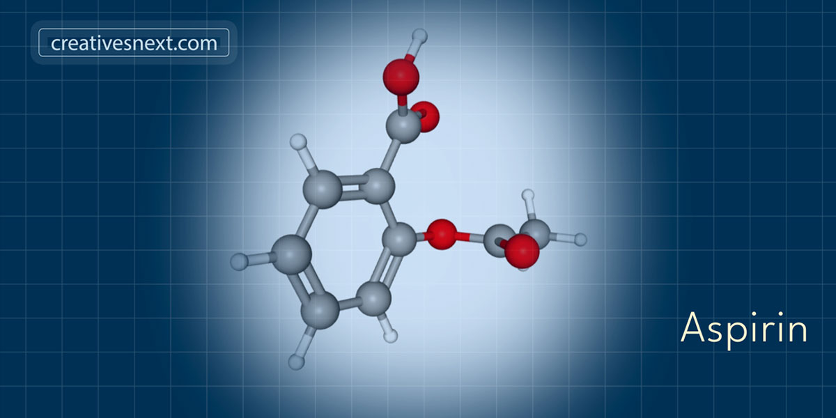
- Get into the PubChem. I typed in Aspirin and got to the page with its 3D molecular structure. To get to an animated 3D molecule, here is the Aspirin, you have to check on Animate.
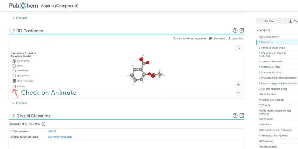
This immediately starts the 3D chemical structures of Aspirin rotate. You may like to go to the full-screen mode for better visibility.
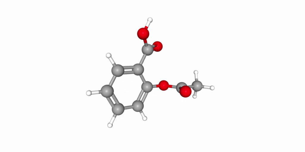
2. At this point, you could use grab the screen using a screen cast program like Camtasia. It will generate a clip usable for further compositing. Here is a screenshot of the rotating Aspirin molecule. Once the animation is screen-captured, you could generate an MP4 file from this and move to After Effects.
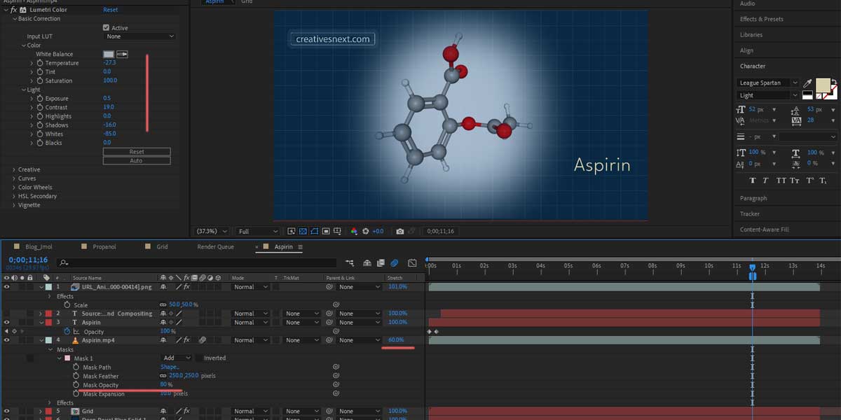
3. Let’s now head over to After Effects and make a simple composite. I won’t take long to explain what I did over there, as it’s a simple composite with the main layer masked over a Grid Background (Col #092843).
One thing I would like to mention. And that is the animation, at its normal speed, is not smooth. I have stretched down the duration to 60% to reduce the jitter. Masked the main layer to get rid of a portion of the white background around the molecule. Cranked down the opacity to 80% and tweaked the color with ‘Lumetri Color’ a bit.
Here is a screenshot with the changes indicated.
The problem with this method is, you can hardly customize the animation. Also, you can’t get rid of the white background around the molecule in totality. Keying out white poses a problem, as the stick and balls have highlights that will get affected while keying out a white sampling from the background.
With several compromises, there are a few upsides though.
- You can get the 3D chemical structures of the molecules in possibly the fastest way.
- It can work well where simple and basic animation is required. Remember, within PubChem 3D conformer area, you may even change the angle of rotation and get multiple versions of rotation. That will give you further options.
- You can show prototypes to your client without having to put in valuable time and effort. A template of 3D animation within such simple and basic compositing will help your client visualize. Once the deal is done, you can work on the details.
3D chemical structures are best controlled within a 3D program. So let’s now head over to one such.
Get your 3D chemical structures into 3ds Max
You already had a molecule and its chemical structures in 3D exported into VRML 3D model from Jmol in the subsection of What next – dive deeper into Jmol & export? with Acetaminophen. Just in case, you want to revisit it, have a quick tour there.
Whether you got it from PDB or PubChem, you had it in a format that’s acceptable in Jmol and now you’re having to convert that 3D file into VRML format to import that into 3ds Max.
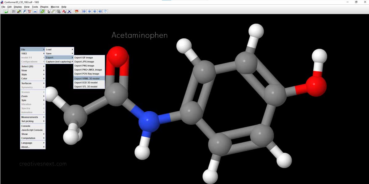
Here we have a quick conversion of Acetaminophen popularly known as Paracetamol (4-hydroxyphenyl acetamide; C8H9NO2) again on Jmol into a VRML 3d model. The extension of the model will be .wrl. In this case, Conformer3D_CID_1983_Acetaminophen.
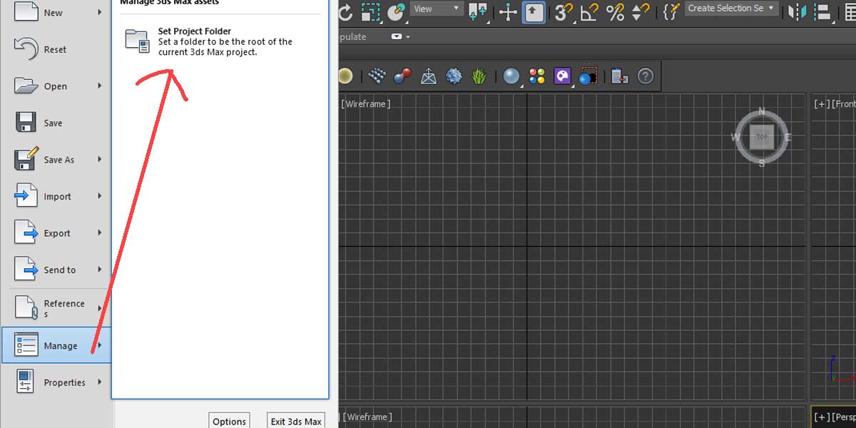
Now, let’s head over to 3ds Max. Before you import the 3d model, you must set the project folder to a specific location. Max creates a number of folders inside its Project folded. And it’s important that you keep all the files that 3ds Max uses keep organized, by keeping all those folders inside an apex folder called the Project folder.
Once the project folder is set, you’re left with the 3d model to import. Let’s import our Acetaminophen in the .wrl format that we have just saved.
There will be an input option dialogue box. Let’s keep all that is checked by default.

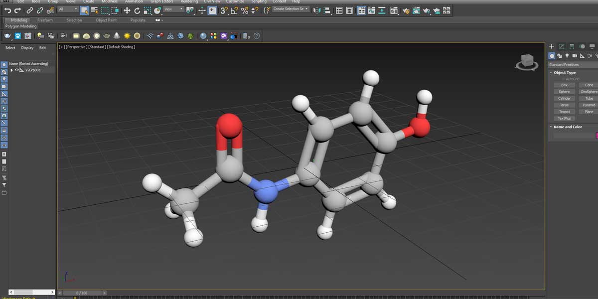
Finally, you have your Acetaminophen molecule imported into the 3ds Max viewport. It comes with a camera. We won’t use that and let’s delete the camera.
Press Alt+W to maximize the Perspective view port. You may press G, in case you want to get rid of the grid in the view port. You also press Z to ‘zoom extend’ the model to maximize the model’s view.
Rotate a Camera around your 3D chemical structure
Instead of a turn table rotation of the molecule, we’ll have a camera rotated around the molecule.
Create a circle in the Top view port around the molecule
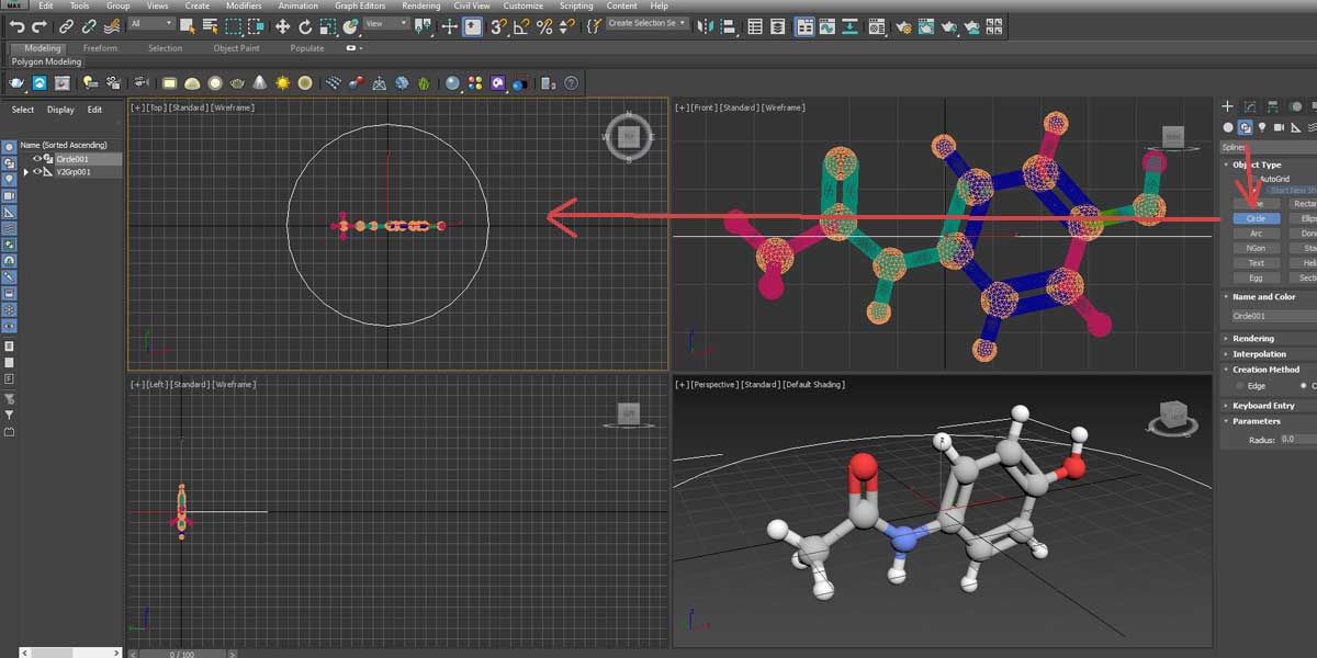
You now create a camera that will rotate around this molecule, along this path. To do this, follow the steps stated below.
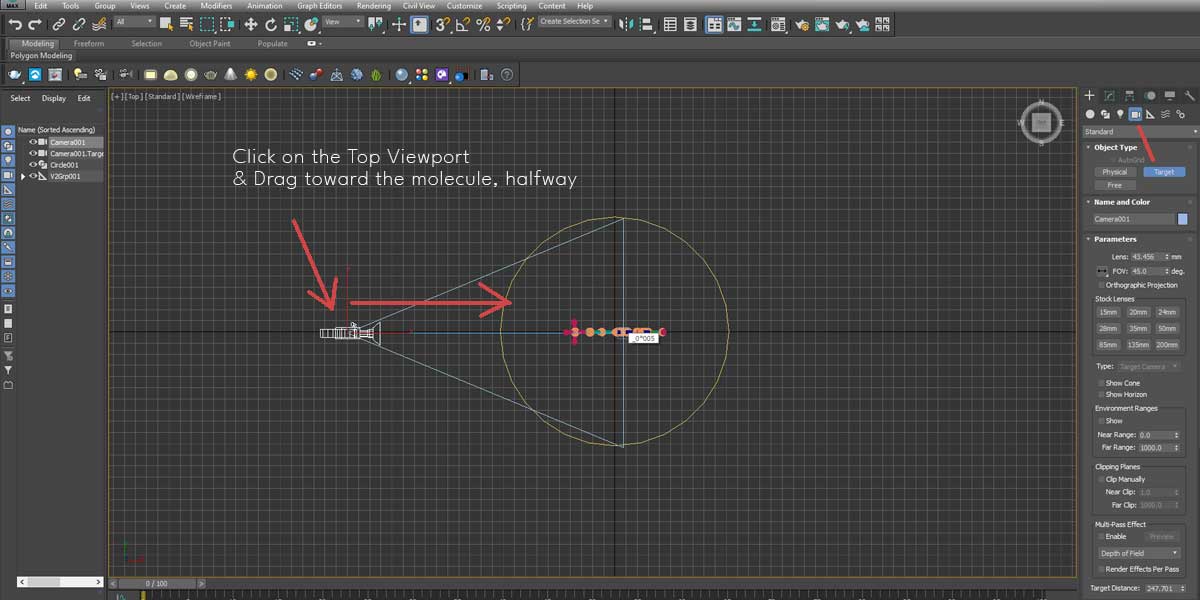
- Create a ‘Target Camera’ by selecting from the command panel
- Click anywhere in the Top View port to create a Camera dragging till halfway to the molecule, approximately to the center of it.
Now, the Path Constraint. This function lets the camera travel along a Path, here the Circle, with its Target fixed, here the molecule. Change to the Perspective view port by pressing P, followed by Alt+W.
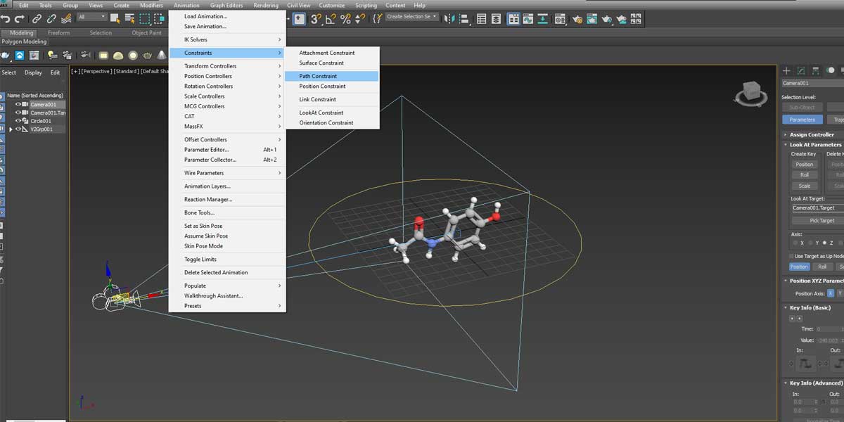
The moment you click or select Path Constraint, with the Camera selected, a dotted line appears with one end fixed to the Camera. All you have to do is to connect the loose end to the Path i.e. the Circle.
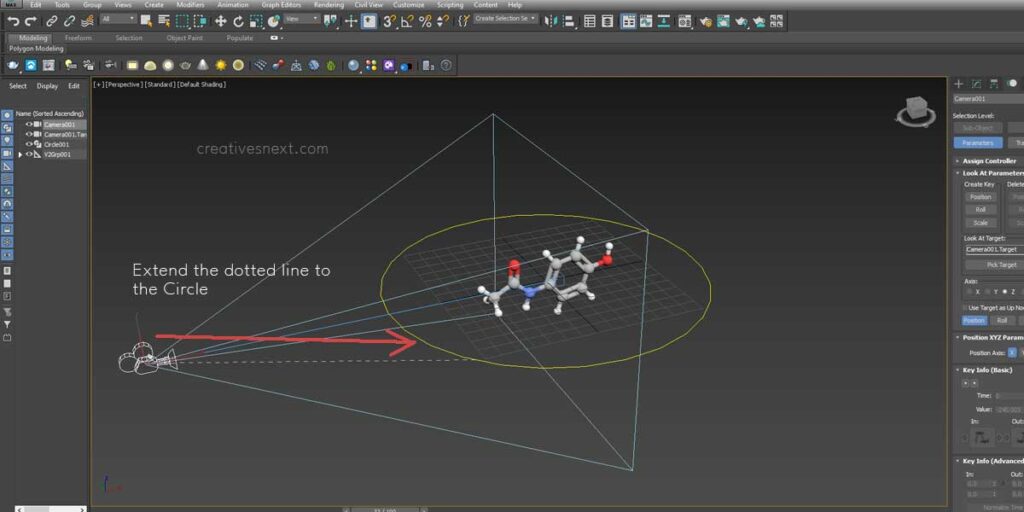
The Camera instantly shifts to the Path with its Target or the ‘Field of View’ remained unchanged. Its FOV sticks to the molecule or rather the center of the molecule. This is the advantage of using a Target camera. Let’s just have a look at the Top View port to check how the camera has changed its position.
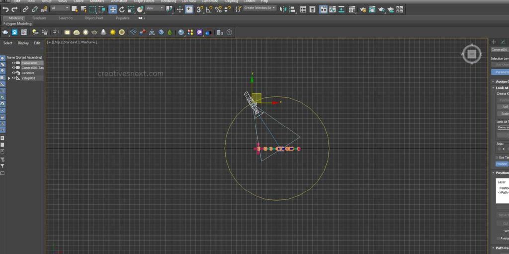
If you now click on the Play Animation button in the right-hand corner, the camera will start rotating. Just change the Left view to the target Camera view picking its name and number, so that you do have a view of the Camera while it’s rotating.
I have made the radius of the Circle a bit bigger, using the Scale tool as the camera’s FOV didn’t initially cover the entire structure. Now, before we see what’s happening out there for Animation through the Camera, a little talk on the Time Configuration function would be helpful.
Set up Time Configuration for the duration of the Animation
Time configuration lets you set the duration of the animation. And it’s good to fix it before you set the Camera and Path Constraint. The Time Configuration button is at the bottom right corner. There are many options here. But for our, purpose, we have left the length at 100, with the first frame being 0 and the last one being 100. The total number of frames count is 101, while the Length reads 100.
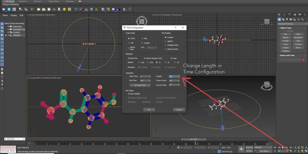
This discrepancy is due to the fact that 3ds Max ignores the last frame while counting the length. You may Re-scale Time even after setting the scene and animation, just in case you forgot. But we’re not going that deep inside 3ds Max and let’s concentrate on setting Time Configuration at the very outset.
View through the Camera & Export Animation
So, this sequence is self-explanatory. You get the Camera rotated along with the Circular Path (Path Constraint) and get animation exported, once you’re satisfied.
A few things to mention for exporting the Animation. I have used the HDTV set up in 3ds Max for availing video size at 1920 X 1080. Pressing F10 will make you land on the 3ds Max Render Setup dialogue box. Also, I have used some free lights from Max as the default lights were inadequate to remove the shadow from one end with respect to the camera.
The frame rate is set to 30 FPS in Time Configuration Dialogue, but that hardly matters and we’ll see that in a moment.
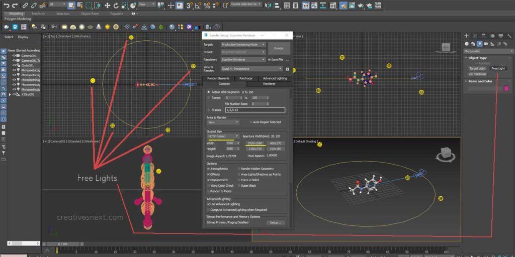
Always create free lights on the Top Viewport first, and then adjust their position in the Front Viewport. You get the animation exported by selecting Active Time Segment on the Render Setup dialogue box (See Under Common). Also, check on Save files under Render Output to export the file. Active Time Segment lets you export animation while a single frame gives you an image. Intuitive, right?
I prefer PNG with alpha, for transparency, and did the same for further use on After Effects. While on After Effects, I used a simple Color Correction using Lumteri Color to make a better look for the 3D chemical structures.
You can easily recognize that the animation is very smooth that you just created and exported from 3ds Max. And it’s pretty obvious. 3ds Max or any 3d program creates amazingly smooth animation if you compare them with the one we had from PubChem.
And there’s a reason.
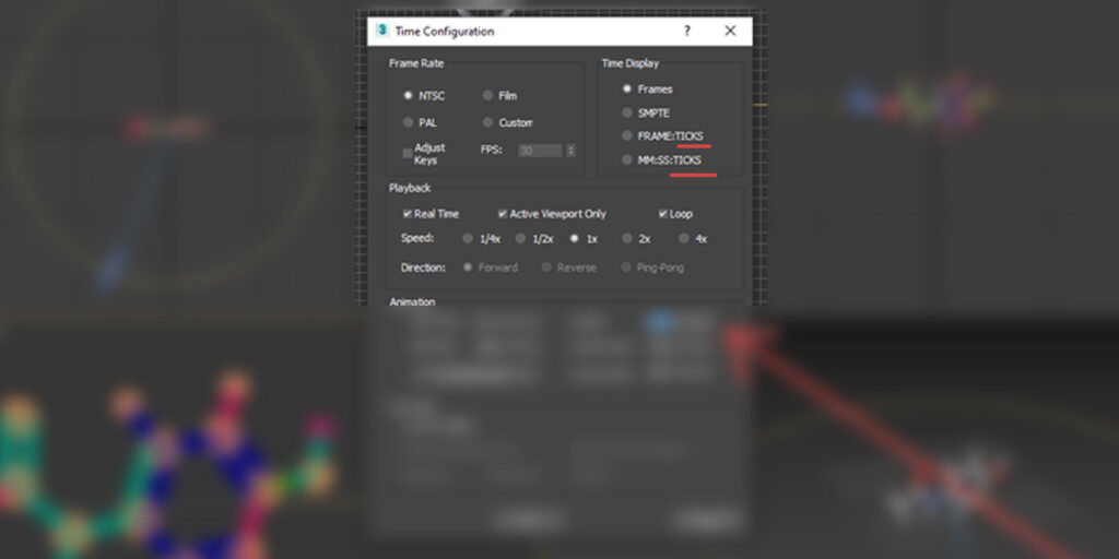
Why the animation of 3ds Max is so smooth?
3ds Max uses TICKS for time measurement. It’s just a unit like a Minute, Second, or Frame. But a TICK is a 1/4800 of a second. So it’s incredibly finer in comparison to the minutes-second-frame measurement system. So, no matter what you have selected in the Time Configuration Dialogue box as the Frame rate or FPS, you may select a different frame rate, let’s say 29.97, in the Render Setup.
Another Instance – A larger 3D Chemical Structure
Let’s now have a bigger 3D chemical structure viz. 1Z31 or the structure of an enzyme-activating fragment of human telomerase RNA. As we have done it several times before, we got the file downloaded from PDB or PubChem, this time too, in a format that’s acceptable to Jmol and then exported it into the VRML format.
Then you import that VRML file with the .wrl extension in 3ds Max. Importing such a giant molecule may take quite some time. So, be patient. Once you land up on 3ds Max, you find this.
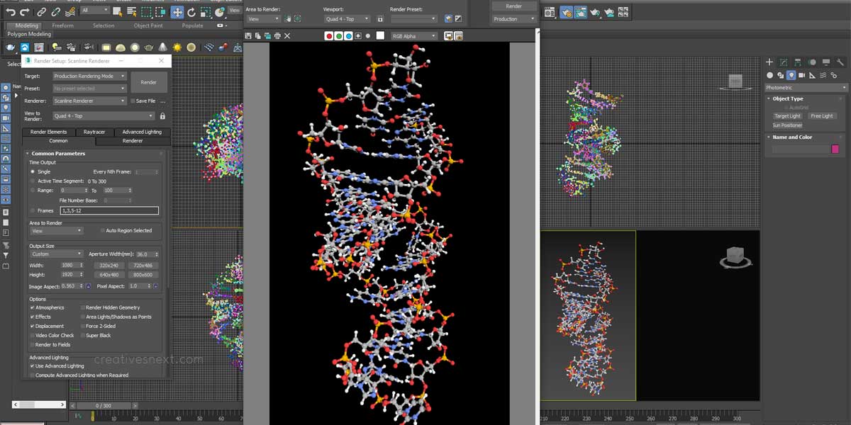
Here, I have changed the Output Size under the Common Tab in the Render Setup dialogue box to 1080X1920 (Custom) for rendering a single frame (F9).
This time instead of rotating the Camera, we rotate the molecule itself. It’s an RNA molecule, so there is an double strand helix. So, kind of elongated vertically. It’s better if you export it in a vertical size, close to 1080X1920.
Here is an output. On the left is the composited, PNG sequence (with Alpha) on After Effects, while on the right is the screen cast of the molecule rotating in the Perspective View port of 3ds max.
Even a simple table turn rotation is good enough for an explainer, that talks about the molecule or the substance that has an aggregate of such 3D chemical structures.
1Z31 – Human Telomerase RNA with a Camera rotated around
This giant molecule is a fit case for camera rotation around its 3D chemical structures. Since the RNA molecule, itself, has a double-helix structure, let’s create a segment of arc around this molecule, conforming to the structure of the double-strand helix.
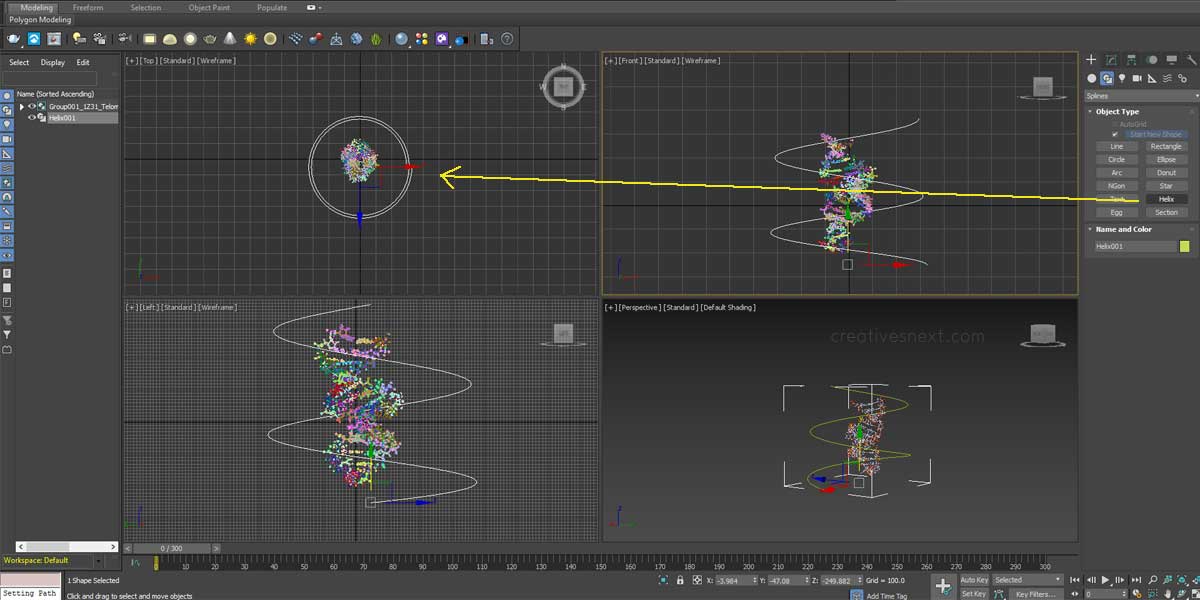
A simple idea. Select the Helix under the Shapes in the Command Panel on the right.
Draw a Helix in the Top view port this time and tweak the parameters of the Helix in the Command Palette. Since you want to rotate the Camera and not the Molecule this time, all you have to do is you have to delete the Keyframes that you created during rotating this Molecule. Otherwise, you can import the VRML file afresh in a new 3ds Max file and start the Camera Setup.
If you want to work on the same 3ds Max file, just turn on the Auto key under the Animation controller and right-click on the Keyframes. There should be one at the beginning.
Once you’re through with the helical path, now it’s time for adding Target Camera and Path Constraint operation.
This time I have changed the Time configuration Length to 600. So let’s have a look at how it comes. First, a screenshot of the Max operation and then the exported image sequence composited on After Effects.
Compositing of 3D chemical structures: Using an After Effects Expression
This time we’ll create a composition using After Effects Expressions. I have obtained this expression from Dan Ebbert’s motionscript.com. Almost all After Effects users are indebted to Dan for his amazing contribution in terms of expressions and their use.
Here is an idea. A simple photograph of a Drug, let’s say, Paracetamol appears followed by four lines, two vertical and two horizontal creating borders along an increasing rectangle. And this rectangle or the master composition will have 3D chemical structures and animation.
Let’s have an image, first, of what is about to come up.
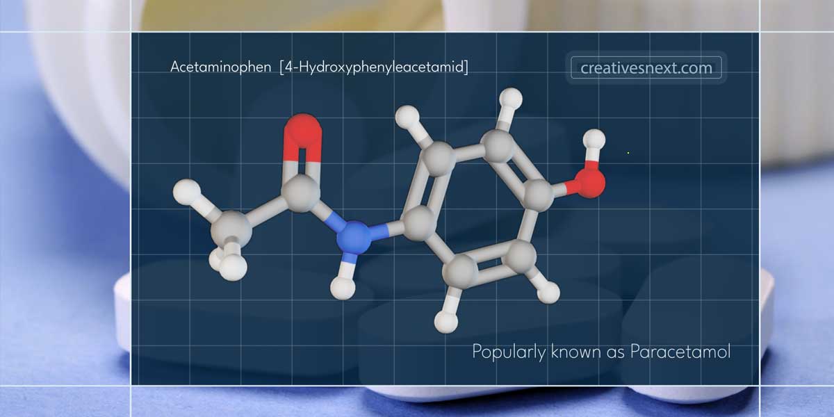
Compositing makes a raw 3D model or simulation visually presentable. When you import an image sequence from 3ds Max or from any 3D program, they usually come without any background. And that’s done on purpose. You don’t use a 3D program for adding such compositing elements there.
You add this over here at After Effects or any other program alike. This background image, the grid, and the borderlines with a rectangle within are what compositing elements that make a 3D render integrate with a scene or composite.
Breakdowns
As you can see in the above image, here are the four lines that make the border of a rectangle area or composition that holds the 3D chemical structures.
Let’s refer to the rectangle composition as master. We also create two vertical lines for the borders on the left and right and create a pair of horizontal lines upper and lower.
Let’s apply the following expression to the position property of the lower horizontal line:
m = thisComp.layer("master");
[width/2,m.position[1] + (m.height/2)*(m.scale[1]/100)]
Apply the following expression to the position property of the upper horizontal line:
m = thisComp.layer("master");
[width/2,m.position[1] - (m.height/2)*(m.scale[1]/100)]
Let’s now apply the following expression to the position property of the right vertical line:
m = thisComp.layer("master");
[m.position[0] + (m.width/2)*(m.scale[0]/100),height/2]
Apply the following expression to the position property of the left vertical line:
m = thisComp.layer("master");
[m.position[0] - (m.width/2)*(m.scale[0]/100),height/2]
You may create a composition with blue background and grid to lay the image sequence of the 3D chemical structures that you got from 3ds Max. This simple composting can nicely get along with a narrative.
Be it a science explainer video, e-learning material, or pharma promotional content, this simple style goes well with the videos meant for consumption.
Let’s see what the final composite looks like.
The possibilities of compositing with 3D renders are endless. Here, I have used a simple yet presentable method to embed the 3D rotation of the molecule into a decent background. The expression used has added a dimension to the animation. Content creators are always on the lookout for new styles and treatments that render their output up for consumption.
Conclusion
In this concluding piece of 2-part content on How to create and Animate, I tried to explain a few things. Maybe a list at the end would be helpful for all of us.
We started with Jmol, a Java-written program that can view, edit and export 3D chemical structures, and delved into online databases like Protein Data Bank and PubChem. We used Jmol and 3ds Max to create, edit and animate the chemical structures in 3D. Finally, we created a composite on After Effects using the 3D renders.
- What is Jmol?
- How to create chemical structures in 3D using Jmol?
- What next? – dive deeper into Jmol and export
- A simple composite in After Effects with exported image [from Jmol]
- How to get 3D chemical structures from online databases like RCSB PDB & PubChem?
Part 2
- Screen capture of 3D chemical structures from PubChem
- Get your 3D chemical structures into 3ds Max
- Rotate a Camera around your 3D chemical structure
- View through the Camera & Export Animation
- Why the animation of 3ds Max is so smooth?
- Another Instance – A larger 3D Chemical Structure
- 1Z31 – Human Telomerase RNA with the Camera rotated around
- Compositing of 3D chemical structures on After Effects
I haven’t put down every tit bits on After Effects here, assuming as a content creator you have exposure. Still, if you’re not familiar with the procedure, please leave a comment and I’ll update this blog any time soon.
Please share this post. And also, please don’t forget to make comments to write down your take.