Texture Mapping Patterns in 3ds Max – Part 3
Published on 24 April, 2024
Introduction
The texture mapping patterns in 3ds max are the key things of material creation for any object or scene prop.
While Autodesk’s 3ds Max offers many different mapping techniques for generating texture mapping, we’re focusing on the most used mapping channels of the program.
In the ongoing series, we have already covered quite a few mapping techniques in the Part 1 and Part 2. In this piece, we’ll focus on some of the mapping patterns that deal with the reluctance and refraction properties of an object.
We’ll also delve into the use of falloff map in 3ds max to create shaders that are useful for realistic scene development and visualization.
If you haven’t gone through the previous articles on this series, the Part 1 and Part 2, it’s better to have read those before getting on to the use of reflection, refraction, and falloff mapping for material creation. This would help get a clearer hold of the texture mapping for surface material of the objects.
While the concepts, I am about to discuss holds universally for any version of Max, you may refer to 3ds Max 2019. On the material front and renderer, I’ll mostly use Max’s default scanline renderer and apply standard material. the main idea is to get to the texture mapping patterns in 3ds Max.
Table of Contents
Use of the Reflection Branch for Texture Mapping Patterns in 3ds Max
Reflection mapping comes into effect when you need to create a shining surface of an object. In reality, the objects that reflect light from its surface have a degree of reflectance, instead of being fully reflective or absorptive.
And for that, we need to control the amount of shining of a surface by adding a map in the reflection channel in 3ds max. The textures of metal bodies or plastics do offer such instances where there are varying degrees of reflection of light from its surface.
In this segment, let’s start with the simplest form of texture mapping patterns in reflection branch of mapping.
Apply Bitmaps for the Use of Reflection Map in 3ds Max
While a mirror reflects the light rays fallen upon it fully, there is hardly any reflection from a tree trunk or its bark. Most objects fall somewhere in between.
Let’s have a bowl with simple diffuse color setting along with some Specular Highlights. The reflection branch, by default, takes
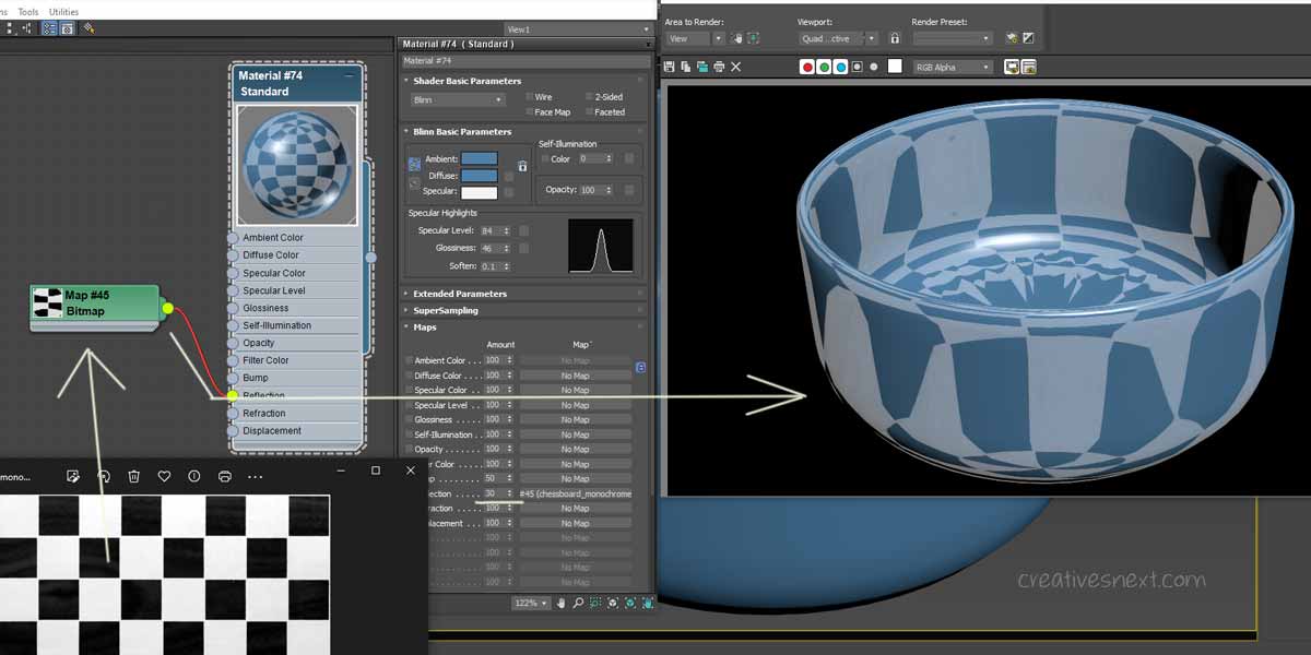
100 as the amount and cranked that down to 30. Let’s tweak the Bitmap parameters a bit. Just double click on the Bitmap to open the Maps roll out.
How to control the Blurriness in Reflection Map?
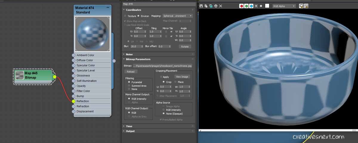
There are two parameters for controlling the Blurriness in the reflection mapping channel. One is Blur and the other being Blur offset.
The Blur controls how fuzzy the map looks from the viewer. The more the amount of Blur is, the greater fuzziness of the bitmap. The amount of Blur sets how near or further away the map is. So, the blurriness of the map is the related to the distance of the map position from the viewer.
Therefore, it’s a function of the depth between the map and the onlooker.
By default it remains 1 and I have increased this to 20. You get the impression of a blurred out bitmap. Crank it up and down to see how it effects the change in the map.
On the other hand the Blur offset controls the blurriness without considering the depth between the map and the viewer. By default it is 0 and just assigning a decimal value lets us have a blurred out map. Let’s crank down the Blur value to 1 and assign 0.2 to the Blur offset and see the effect.
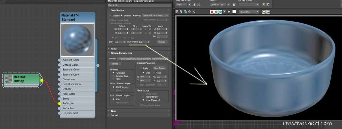
The Blur offset, unlike Blur, doesn’t take depth into consideration and is much more sensitive even at the slight change of the values.
Also, try changing Mapping in ‘Environ Mapping’ to see how it changes the Blurriness. I have stuck to the Spherical Environment.
Use of Reflection Map on a metal surface
- Use extended primitive > Taurus knot. I have assigned sides value as 32.
- Use a dark diffuse color
- Make sure in the Render Set up you have assigned Scanline and the renderer and is using Standard material. Also, I have checked on two features in the Render Set up > Common > Options > Force 2 Sided & Super Black
In the next step, I have gotten a few images from freepik, which I shall be using as the reflection map on the surface of the Taurus knot.
- Add the image downloaded from freepik as a bitmap on the stale material dialogue box.
- Add the bitmap to the Reflection channel of the material dialogue box.
- By default, the reflection map takes an amount of 100. Let’s change that to see how it affects the surface mapping.
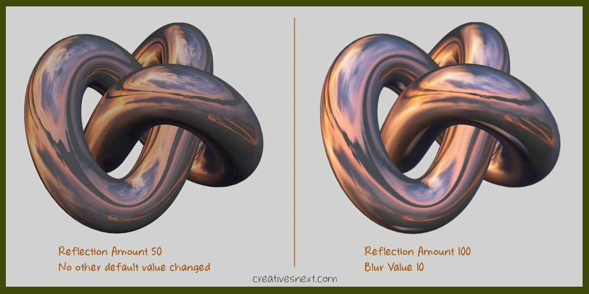
See how the texture mapping patterns in 3ds max changes with little adjustment in the map settings. The image image on the right clearly has much more metalness than the one in the left.
The shining metal surfaces always emanate rays of light in the form of reflections and the use of reflection mapping in 3ds max lets you control the amount and nature of ambient reflection toward achieving realism.
One thing you must remember while selecting a bitmap as the reflection map type, consider getting a detail and eventful photograph. By that , I mean to say an image with a lot of variations and contrasts, unless otherwise intended on purpose.
On the other hand a flat tonal image will hardly produce a noticeable reflection on the metal surface failing a realistic production. Let’s see both the images side by side that I have downloaded from freepik.
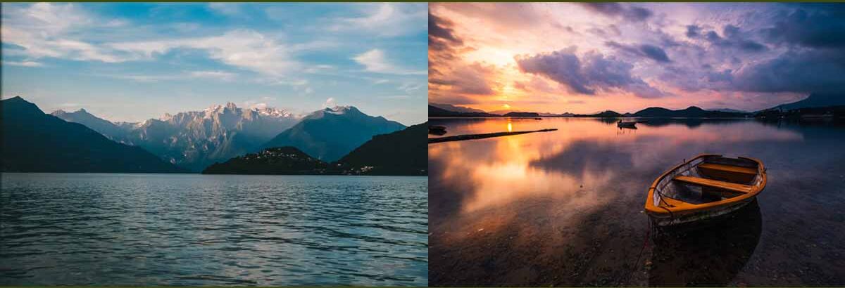
See both the images have wide range of tonal values that can produce realistic reflection upon the metal surfaces. The advantage of the using such images is you can even crop the image inside the Bitmap (double clicking) dialogue box to focus on a specific part of the image and get the contrast or brightness level of that particular area.
Let’s see how the image on the left affects the reflection mapping.
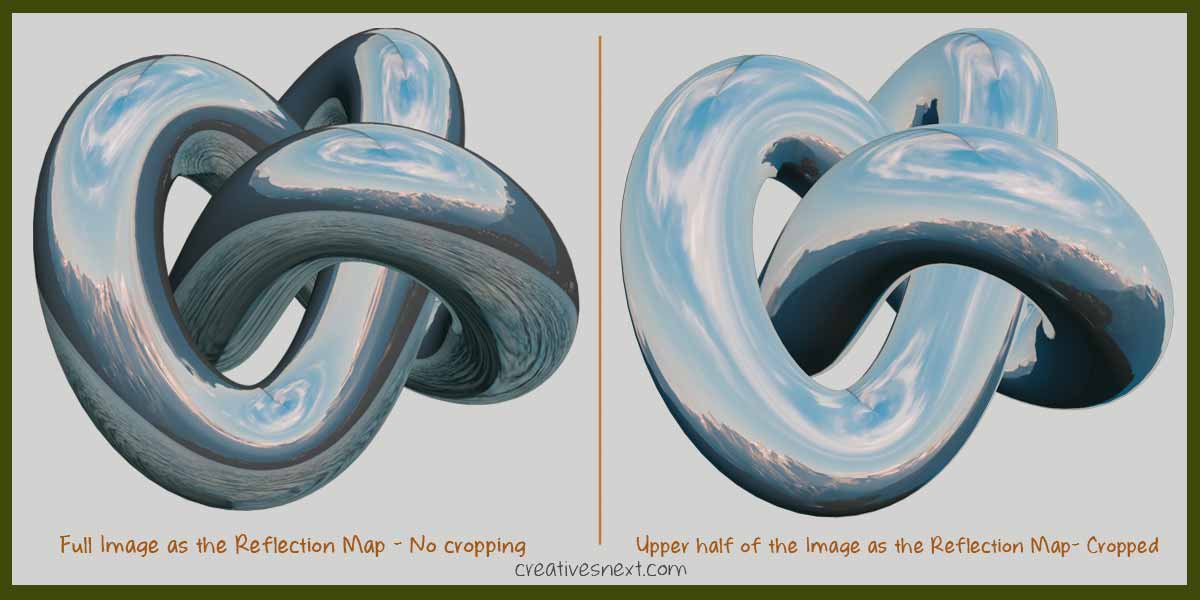
Clearly, you get different illuminations of the metal surface using the image with different cropping. With such busy image you get the chance to crop and bring in different intensities of light upon the surface.
Reflection map is one of the key things in producing realistic metal surface the more you practice with the map roll out settings, a better hold you’ll have over generating texture mapping patterns in 3ds max in reflection branch.
While there are many texture mapping patterns in 3ds max, creating a realistic surface material for an object requires using combination of mapping channels. With reflection, there is another object property that is extremely useful. In the next segment we’ll discuss refraction mapping in 3ds max.
Refraction Mapping in 3ds Max for realistic surface material
From physics, refraction is an object property that bends light passing through it. Technically speaking, this bending occurs due to the light travels at different speeds in two different media.
In plain language, this bending of light takes place inside the objects and that calls for creating a bit transparent surface for the object.
Now certainly, there is varying degrees of transparencies and that demands use of refraction mapping in 3ds max with different tricks and techniques. The refraction mapping parameters let you control how the ambient light with its color appears inside the object.
There are a few ways to create refraction of an object inside 3ds Max. One is the Reflect/ Refract Map and other being Raytrace. Let’s again work on our Taurus Knot to see how this two works, one after another.
Using Reflect/ Refract Map in the Refraction Channel
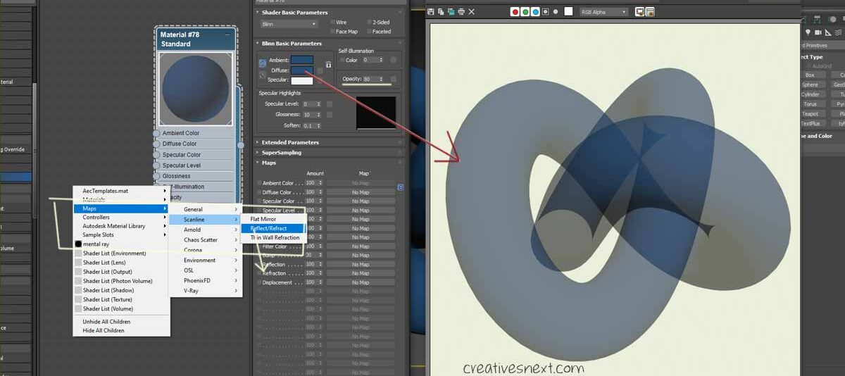
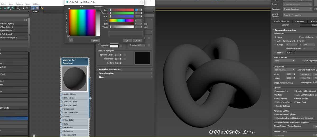
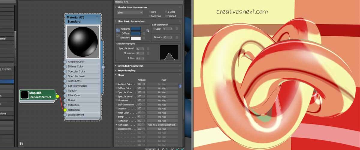
First, let’s make a few changes to the Taurus Knot. i assign and darker Diffuse color value and cranked down the Opacity to 80. I have also used a light yellow color for Background in the Environment dialogue (Press 8).
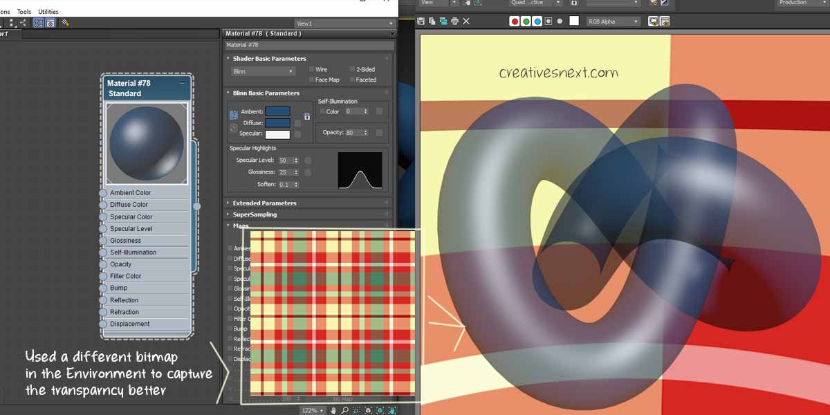
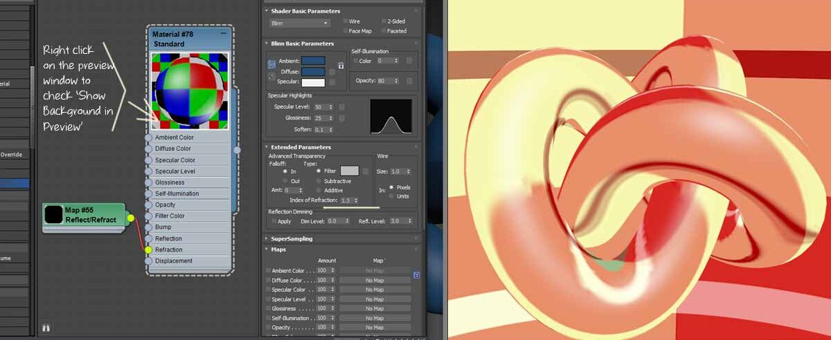
But this looks somewhat misleading in the sense that there is no glossiness in the object surface and the background is flat with no texture to make the transparency look better. Let me tweak a few things. Crank up the Specular level and Glossiness to 50 and 25 respectively and use the bitmap, as shown below in the Environment.
Now, in the Slate Material editor right click and go to Maps> Scanline > Reflect/ Refract. This is a particular type of map that we’re about to assign to the Refraction branch.
Now, see the radical change in the surface material. You’re now right in the middle of learning texture mapping patterns in 3ds Max.
Before we modify the settings, try to figure out where you can apply such texture mapping pattern. Objects with high specular highlight and translucent surface calls for using such mapping channels in 3ds max and respective maps. Let’s now modify this Reflect/ refract map parameters to attain some realism.
Let’s first tweak the level or index of refraction inside Extended Parameters roll out. The index of Refraction or IOR measures how the medium bends the light or refracts. By default it remains 1.5 which is the IOR of glass. Let’s change it to 1.3 which is the IOR of water and see how it affects the surface.
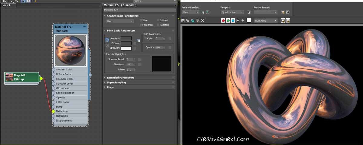
An IOR of 2.4 is that of diamond, while 1.9 is for Gold. Let’s try this time with the IOR of gold.
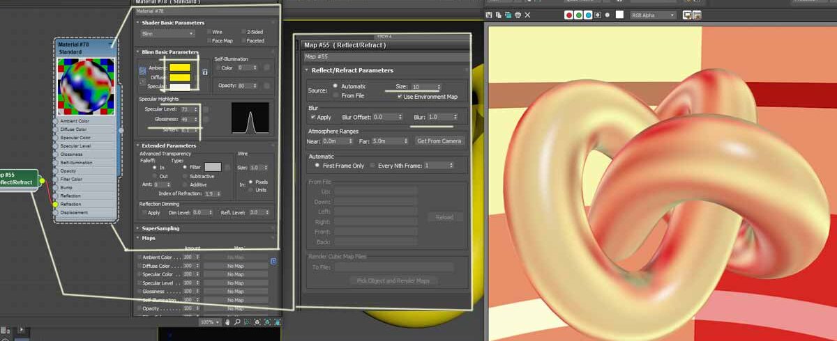
This time I have changed a few things.
- Changed the Diffuse color to the RGB value of gold.
- Cranked up the glossiness a bit
- On the Extended Parameters roll out, assigned IOR as 1.9
- With the Map roll out i.e. double clicking Reflect/ Refract map, used the default Blur value of 1 and Changed the Map size to 10
This has yielded completely different a texture mapping pattern for the surface material. There are list of IORs available online and you can get whatever required based on your need. With Reflect/ refract map, there is also Ray trace map that used a different algorithm when used in the Refraction channel.
Using Raytrace Map in the Refraction Channel in 3ds Max
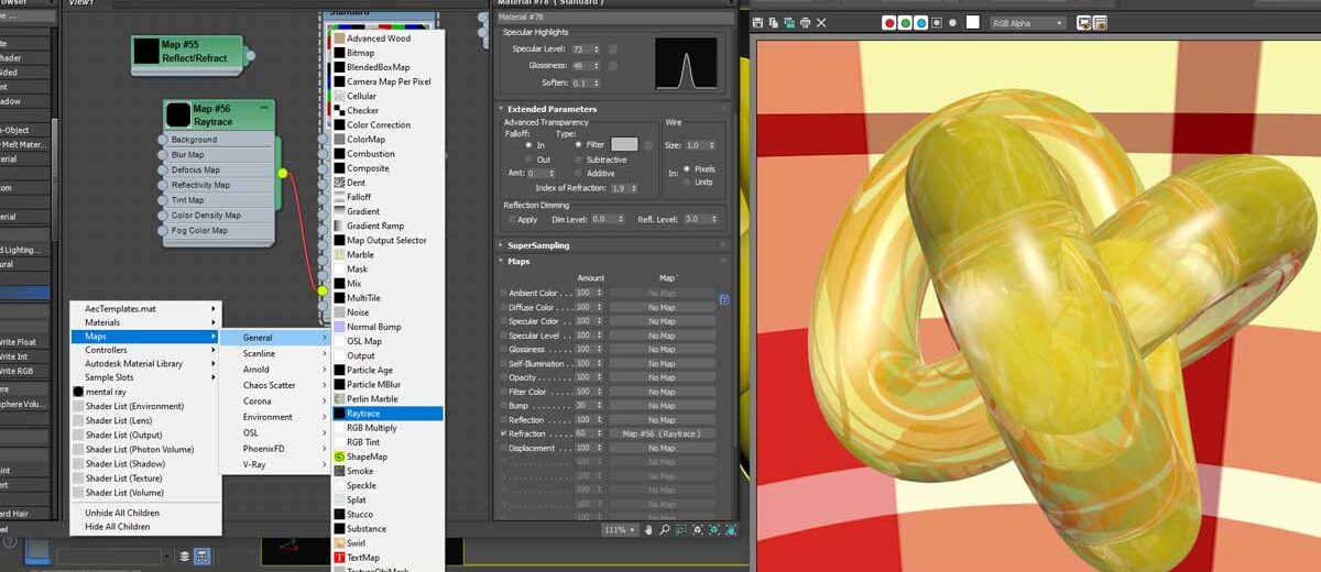
You can assign a raytrace map to the Refraction channel by right clicking on the empty space in the Material dialogue and then choosing Maps> General > Raytrace. The default value of the Map amount is 100 which is quite pronounced and I have therefore cranked it down to 60.
Rendering texture with Raytrace maps takes longer as it involves somewhat intricate calculations compared to Reflect/ Refract maps.
Remember, all the mapping co-ordinates used in Reflection and Refraction branch for generating texture mapping patterns in 3ds max use Global co-ordinates and are not affected by the positional shift of the objects.
Using Raytrace Map in 3ds Max – Create Mirror like Reflection
Apart from the method of calculations in rendering the Reflect/ Refract Map and the Raytrace map, there is a significant difference between the two.
In the case of the Raytrace map used in the Refraction branch of 3ds Max, you can exclude an object within the scene from producing reflection upon the object surface. This is not possible in case of the Reflect/Refract map. Let’s see with an instance.
Now, what’s happening here!
I have created a plane with a curved seam in the background. It’s pretty easy.
Create a plane beneath the Taurus, convert it to an editable poly, select the edge (with loop) and shift drag to create another edge. You have to move this edge (the last one) upward. Get out of the editable poly mode and apply Turbosmooth.
Now, assign a standard material to the plane. Bring a Raytrace map to the Refraction branch of the Mapping channels. At once, you get the reflection. Since the material of the plane has a Raytrace map applied to its Refraction branch, the plane itself, cast its own shadow.
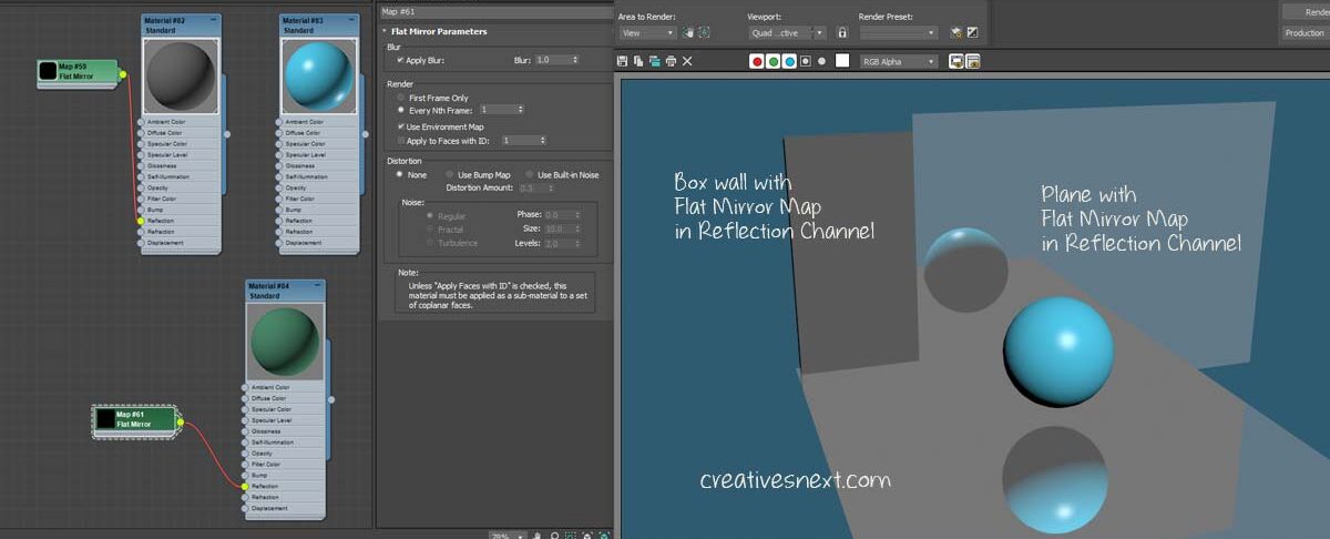
Let’s now create two walls without the Raytrace map applied on them to see how it works.
Clearly, the walls with no raytrace map applied are not producing mirror like reflections. Even the plane (with curved surface) is now showing the reflections of all the scene props including its own, the walls’ and the Taurus knot’s.
As we have already discussed that unlike the Reflect/ Refract map, the Raytrace can exclude a scene geometry from producing its reflection. Let’s now see, how we can achieve that.
Using Raytrace map in 3ds max to exclude scene geometry from reflections
In the above image, we have seen all the scene props are creating reflections as usual in the case of a mirror. The plane with the raytrace map is now acting like a mirror. Now, to exclude any geometry we have to go to the Raytrace Map roll out. Double click on that and get to the Local Exclude.
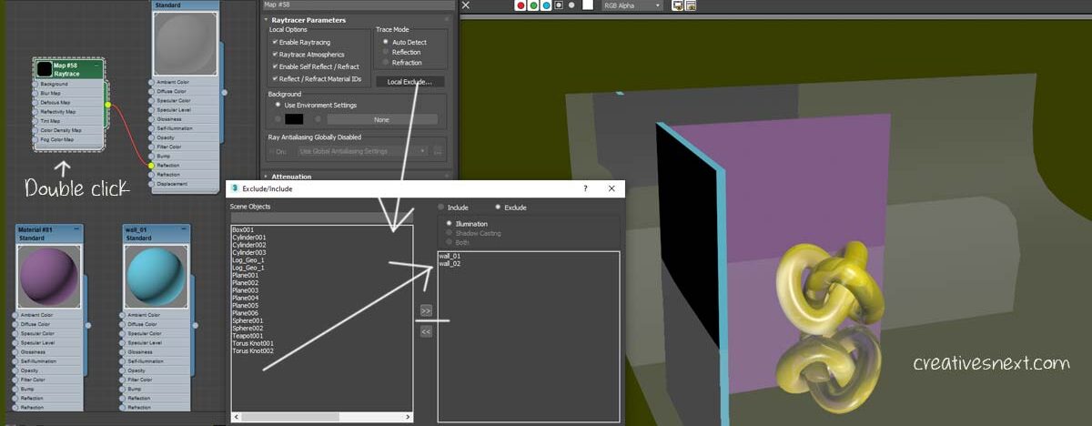
Pretty simple. In this screenshot, I haven’t yet rendered. So let’s see what’s the effect of rendering.
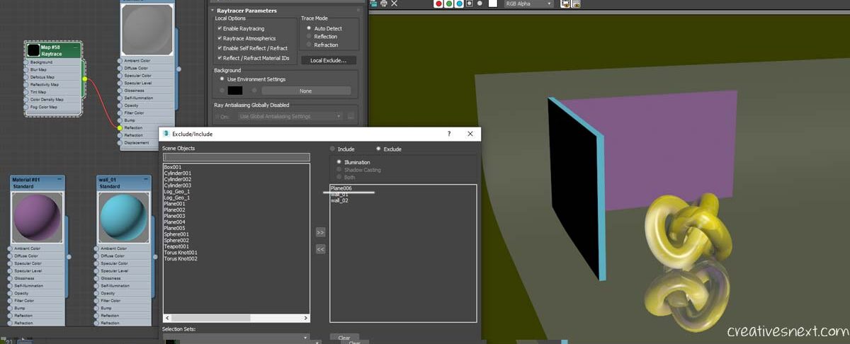
Not only did I exclude both the walls, I have further excluded the Plane (plane006) itself and then rendered. Now we only have the reflection of the Taurus knot over the plane.
But, in real world often wee see the reflection get gradually blurred out and doesn’t cast as sharp and crisp a reflection as we saw in the above image. So let’s now see how we can phase out a reflection from the source or object.
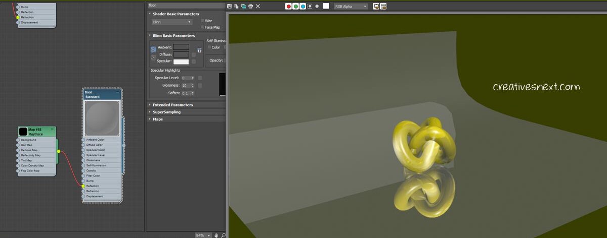
Use of Reflection map in 3ds Max – Apply a Flat Mirror Map to create mirror like Reflection of the Scene Geometries
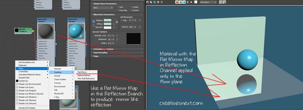
What did I do here?
- Created three objects, one plane, one sphere and a wall
- Applied standard material to all of them, with a special one to the floor plane (with a dark diffuse color).
- Get the Flat mirror map and add that to the reflection branch of the floor plane.
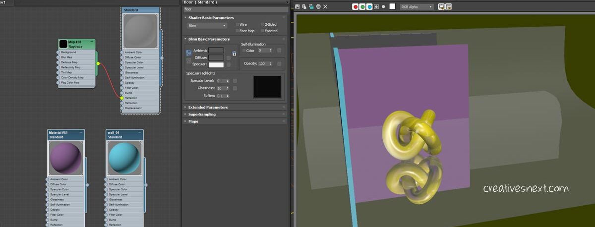
As usual, there are other parameters that you can control, like Blur etc to tweak the nature of reflections. But unlike a Raytrace map, you cannot exclude a scene geometry.
Also, the Flat mirror works on a plane and and not on a 3d object. I have applied the same material with the Flat mirror map in the reflection branch onto the wall. It didn’t work. But the moment I introduced a vertical plane between the wall (Box) and the sphere and applied the floor material, it casts the reflection.
There are many ways of forming different texture mapping patterns in 3ds max. We have just seen using a raytrace map in the refraction channel.
Add Falloff to create blurred out reflection while using Raytrace map in 3ds max
You can just play around with hell lot of features inside the raytrace map dialogue while generating various texture mapping patterns in 3ds max.
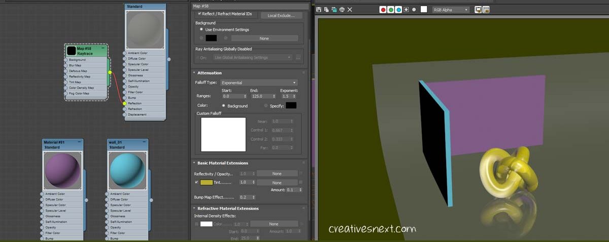
What did I do here? Under Attenuation there are different Falloff types like, Linear, Inverse Square, Exponential and Custom Falloff. I have chosen Exponential and changed the default value of 100 in the End Range to 125 and cranked up the Exponent to 1.5 from 1.
Here, the end range controls how far the shadow will be see. The lower the number, the narrower the portion of the object will be seen in it reflection.
The Exponent value controls how sharp or soft the blurred out end of the object will be in its reflection. The higher the number, the softer or blurrier will be the reflection, while a lower number will create a sharp and abrupt end, which is somewhat unnatural.
The Raytrace Map has many different parameters. I’ll come back and update this page whenever I’ll find an interesting application of the same. I leave to you at this stage to play around and find many more ways of using raytrace map in 3ds max.
Use of Falloff map in 3ds max
Falloff map in 3ds max is an extremely important feature to create a particular type of shader that is otherwise hard to achieve.
You have seen many medical illustrations where micro-organisms and bacteria are visualized and represented using a typical shader at their edges. You can create this shader using Falloff map.
We shall, in this segment, see how we can use this map in the map branch to generate some unique texture mapping patterns in 3ds max.
Let’s get straight into to the business.
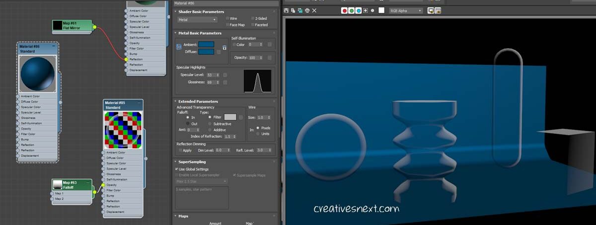
What are the things happening here?
- I have created a few object with a simple background, choosing Metal as the shader basic parameters, with a dark blue as the diffuse color.
- Now you have to bring the falloff map and add that to the opacity channel. I have assigned white as the diffuse color and applied the material to all of the scene props, saving the background plane.
- Use of falloff map in 3ds max creates shader at the edge with a particular type of shader. It distinguishes the viewing normals from the one away from the viewers. Now what does that mean in plain language? The falloff map creates a shader on the object’s surface that differentiates the portion of the object facing toward the viewer from the portion that is away from the viewer.
This is the main function of the falloff map added to the opacity branch. See in the above image the portion of objects that are away from our viewing direction is shaded with white, while those facing directly toward us is somewhat transparent.
The falloff map creates translucency for any object and this map is a 3d procedural map. That means the object’s local co-ordinates do not have any bearing upon the mapping co-ordinates.
Now, you can control different settings of falloff map that i discussed in detail in a previous post on the Medical illustrations with 3ds Max. I am not repeating all those details here as Google might penalize for posting similar content.
Conclusion
Texture mapping patters in 3ds Max is really an interesting arena for realistic surface finish. And in this piece, I have mainly focused on the Reflection, Refraction and Raytrace mapping. I have also barely scratched the surface with the use of Falloff map in 3ds Max.
I’ll keep on updating this blog with more applications should I come across any interesting or useful instance. There are many other map types that are used, some widely and some not-so-widely.
Hope this piece has made you get to the concepts of a few texture mapping patterns in 3ds max and their use. Please don’t forget to share piece in social media, if you find it useful. Also, please leave comments below if you have any particular thought on the map types I have discussed here.
The more we engage, the better would be our understanding.